Manufacturing case
Alumina heat-exchange components: internal channels from printing to sintering
Six locally logo-edited sample photographs and four process stills illustrate enclosed channels, integrated connectors, printing, cleaning and furnace loading.
Authorized adaptation of a supplied manufacturing case, not a KUNWU test report. Supplier logos were removed by localized image reconstruction; reconstructed texture is illustrative, not original measurement evidence. Rulers and pixels outside the disclosed edit regions are preserved. Four process GIFs are presented as still frames. No pressure, leak-rate, heat-transfer or lifetime qualification data are provided.
1 · Channels hidden inside the body
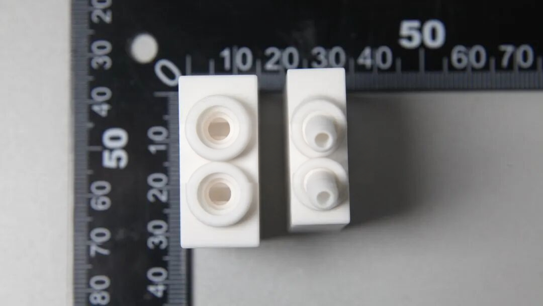
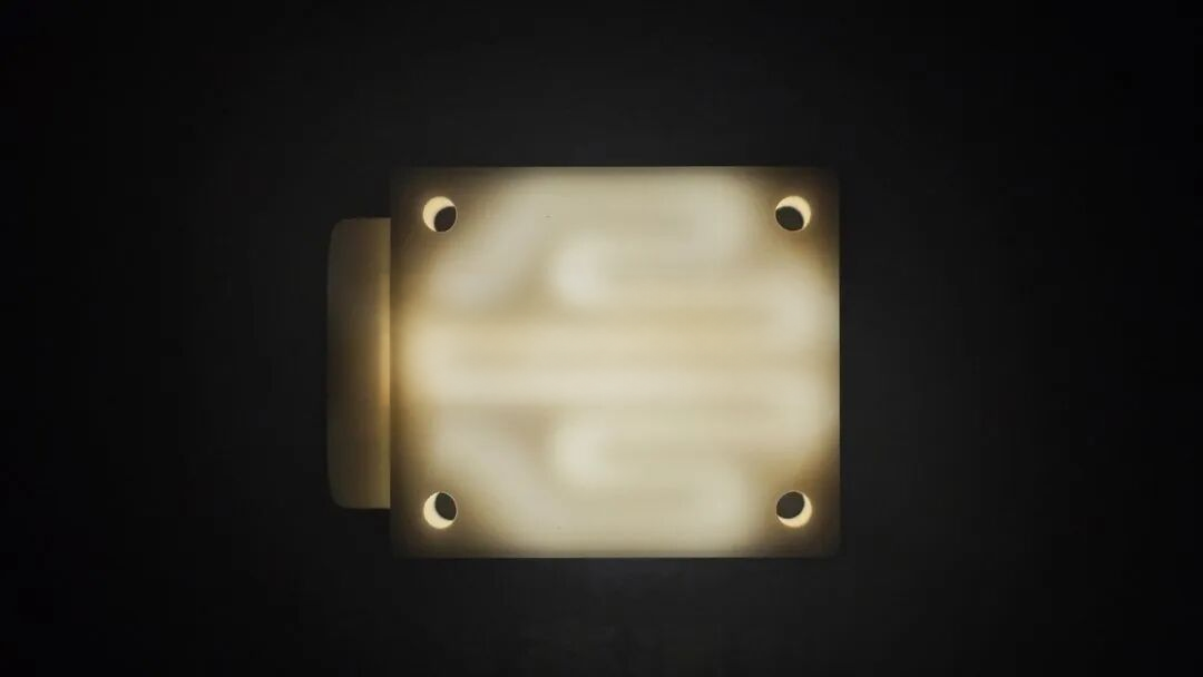
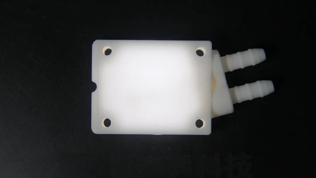
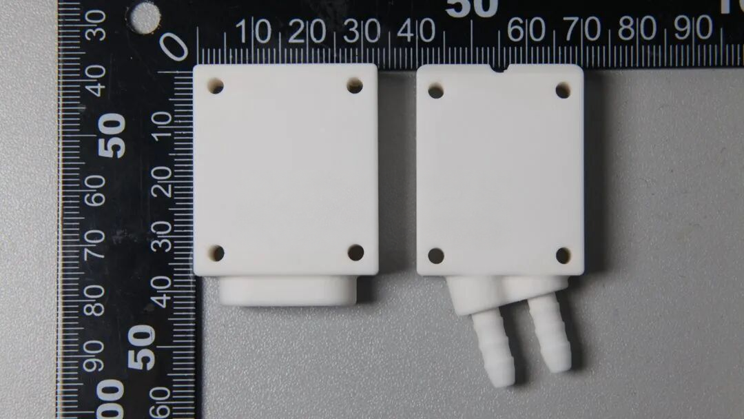
The supplied case shows plate-like alumina components in two connection variants: plain ports and barbed hose connectors. Backlighting through the thin walls reveals the enclosed flow paths and internal partitions. Such cavities are difficult to demold conventionally and cannot simply be machined from the outside without a different assembly route. Layerwise ceramic photopolymerization forms the external body and its channels together.
2 · Integrated ports and repeated builds
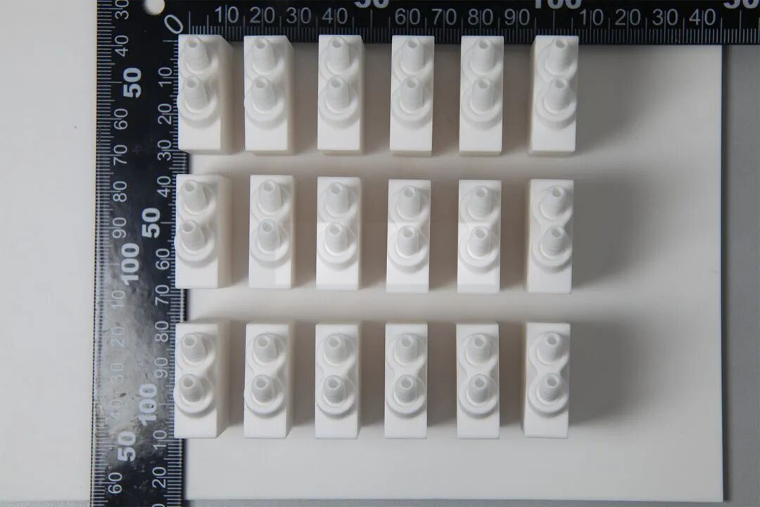
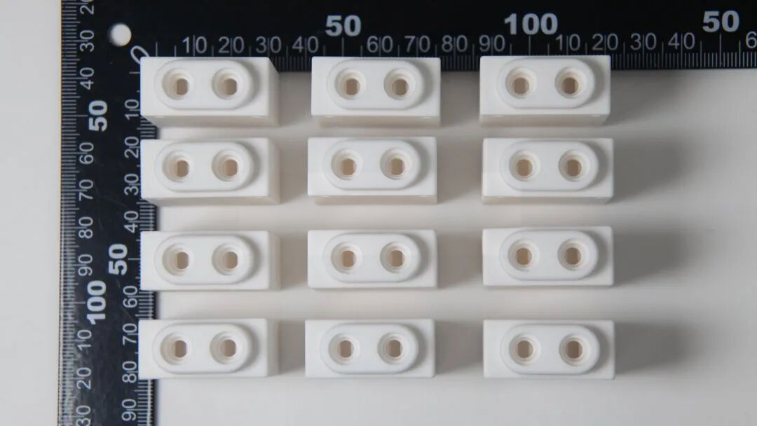
Connectors and four corner mounting holes are integral to the body. Reducing bonded-on fittings can reduce assembly steps and potential leak interfaces, but does not itself prove leak-tightness. Alumina offers electrical insulation and resistance to heat, wear and many corrosive environments; suitability depends on the actual fluid, temperature and surface condition. Arrays of identical digital models allow multiple parts in one build. The source shows batches of both barbed and plain-port versions, not statistical dimensional or production-yield data.
3 · Printing the channel and body together
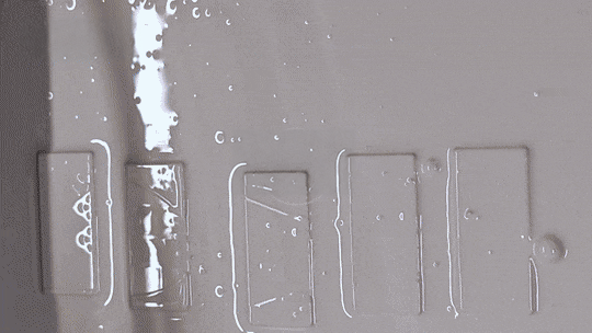
Each sliced pattern exposes and cures the alumina-loaded slurry. Successive layers reproduce both the outside geometry and the enclosed passages, with several parts arranged on the platform. A still frame from the supplied animation illustrates this stage, with logos locally removed. It is a supplier demonstration, not evidence that this exact part was produced on either featured research machine.
4 · Removing fragile green parts
The platform lifts the printed green bodies out of the slurry. They still carry uncured material and have limited strength. Removal must protect thin walls and projecting tubes from bending or local fracture. The second process still illustrates the handling stage, not the complete motion sequence.
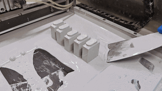
5 · Cleaning the enclosed passages
Spray cleaning removes residual slurry from surfaces and internal passages. For enclosed channels, incomplete drainage or cleaning can leave blockages and create defects during debinding. Establish access, a compatible cleaning medium, drying and an inspection method before committing to the geometry. Do not assume that visible external cleanliness verifies the interior.
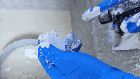
6 · Debinding, sintering and qualification
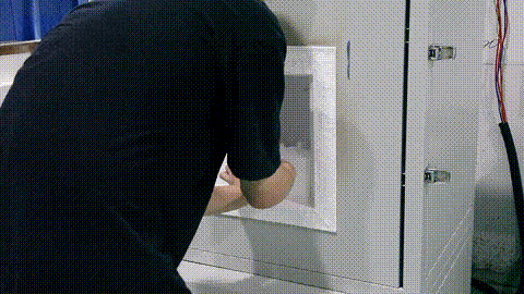
Cleaned bodies are loaded on setters into a furnace for a material-specific debinding and sintering schedule. Binder removal and densification turn the green body into a ceramic component and introduce shrinkage that must be compensated and measured. The final still illustrates loading/handling, not a complete recorded furnace cycle. The case provides no numerical schedule or measured heat-transfer, pressure, leak-rate or lifetime results. Those tests, final dimensions and acceptance criteria must be agreed for an actual heat-exchange project.