Functional ceramics research
90 wt% BaTiO₃: printing programmable three-axis piezoceramic sensors
A research team combines high-solids DLP printing with symmetry-breaking microstructures to encode directional force sensitivity in monolithic ceramic sensors.
These values belong to the cited BaTiO₃ research and its test conditions. The experimental machine was ADT-3D-ZP-Printer-96-50; the study does not validate the new DD50 or guarantee the same performance on another printer. Biomedical and autonomous-system uses are research prospects.
- BaTiO₃ solids loading
- 90 wt%
- Reported piezoelectric coefficient
- >240 pC N⁻¹
- Reported compressive strength
- >340 MPa
- Reported force sensitivity
- 0.42 V N⁻¹
The challenge: high solids, fine features and piezoelectric response
Complex microsystems, including miniature robots and implantable-device concepts, create a need for small piezoelectric sensors that distinguish loads along three orthogonal axes. Directional response depends on both material properties and microstructure. Photopolymerization can form these geometries, but high powder loading, forming accuracy and electromechanical performance are difficult to optimize together. Around 80 wt% solids, many existing formulations reach a turning point: further loading increases viscosity and light scattering, raising the risk of pores, cracks and delamination. The central question is how to turn structural anisotropy into stable and predictable directional sensing while printing a highly filled ceramic.
Study and experimental platform
Jinsong Leng’s team at Harbin Institute of Technology proposed a solid-loading-maximized precision additive-manufacturing strategy and a three-dimensional orthotropic design framework based on parameterized symmetry breaking. Peipei Wang is the first author; Xin Lan and Yanju Liu are corresponding authors. The paper identifies a high-precision dual-cylinder, descending-platform DLP machine, ADT-3D-ZP-Printer-96-50, for producing ceramic green bodies. The result combines a 90 wt% BaTiO₃ formulation with a programmable mapping from topology to stiffness and piezoelectric sensing response.
1. Slurry preparation, debinding and sintering
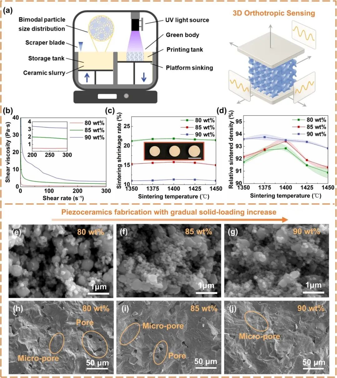
The first figure follows the preparation and sintering route. The printing schematic is paired with rheology at different solids loadings, sintering shrinkage, relative density, and SEM images before and after sintering. These panels are essential for interpreting the reported near-defect-free forming: solids loading alone does not establish density or part quality. The formulation and thermal route must be evaluated together.
2. Electrical comparison with dry-pressed ceramics
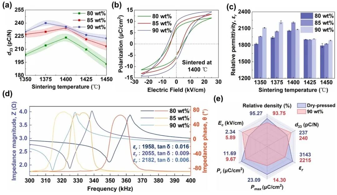
The reported piezoelectric coefficient exceeds 240 pC N⁻¹. The second figure compares piezoelectric coefficients, polarization hysteresis, relative permittivity and impedance spectra, then benchmarks printed material against dry-pressed ceramics. The source describes their combined performance as comparable. This does not mean that every measured property is identical; the original radar plot and test conditions should guide the comparison.
3. Mechanical strength and forming accuracy
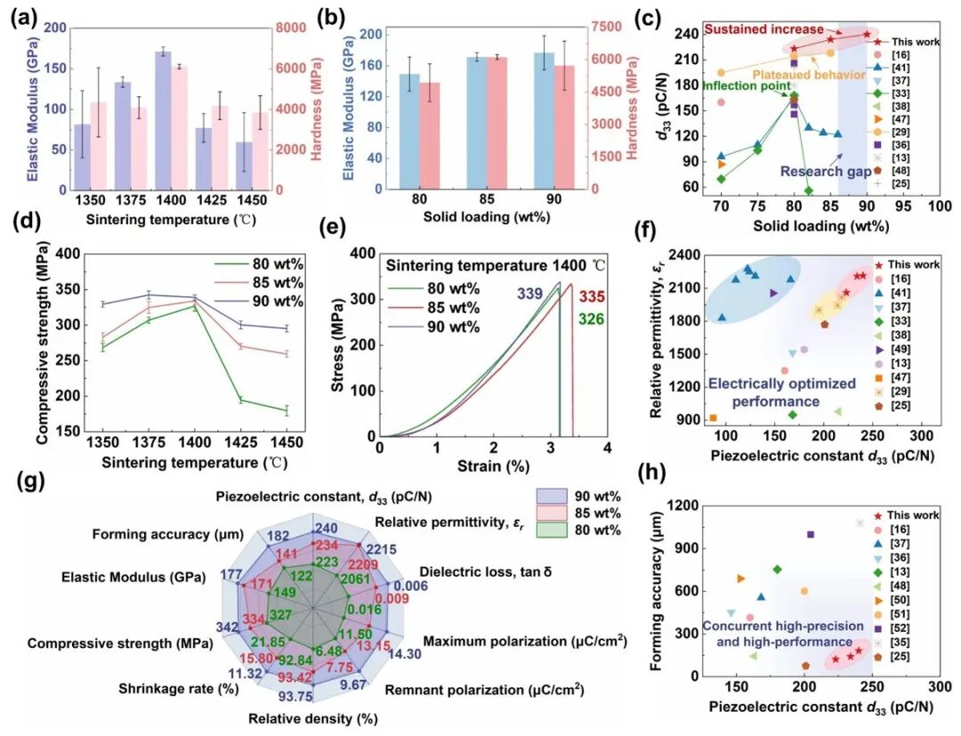
The research reports compressive strength above 340 MPa alongside electromechanical performance comparable with conventional dry pressing. Figure 3 includes modulus, hardness, stress–strain curves and comparisons with earlier work. Monolithic devices have an edge length below 5 mm and features below 200 μm. The latter is a feature-size result for the experimental structures, not a printer’s guaranteed dimensional tolerance.
4. Dynamic response
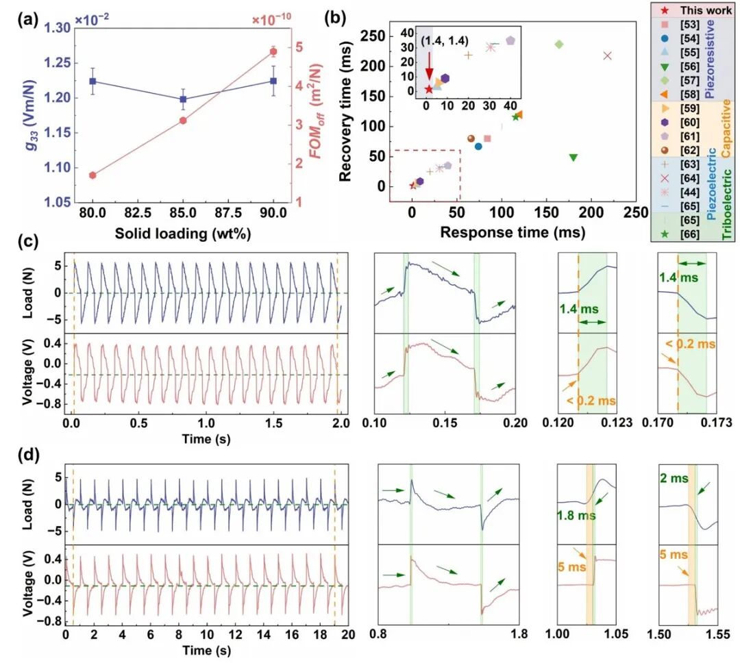
The integrated sensors reach reported force sensitivity of 0.42 V N⁻¹ and linearity R² > 0.999. The study describes near-zero delay and good synchronization between the loading waveform and output voltage. Figure 4 compares g₃₃ and FOMoff with solids loading, response/recovery times and voltage traces at different loading frequencies. These dynamic tests help assess temporal response rather than only a static coefficient.
5. Programmable orthotropic sensing
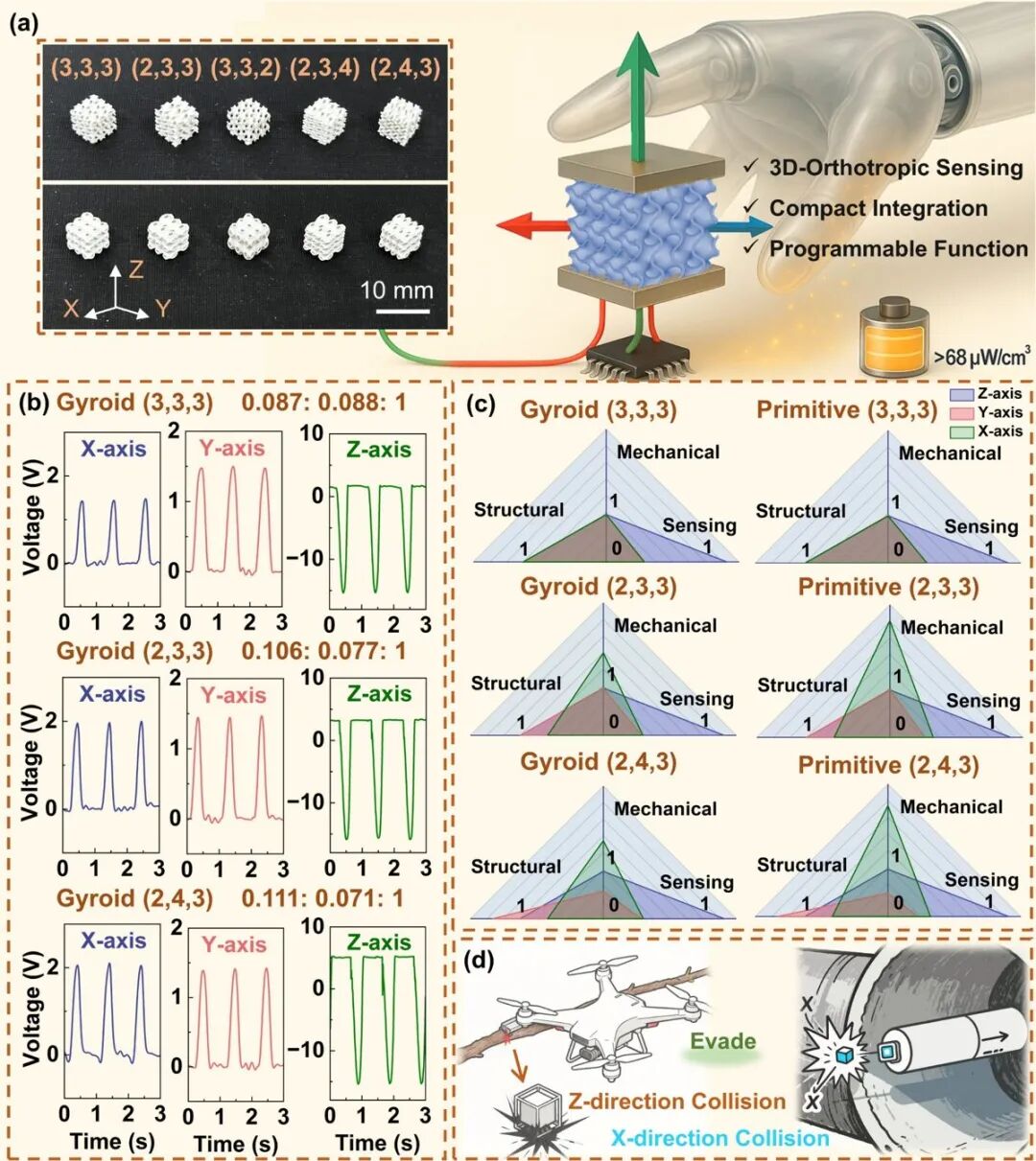
Parameterized symmetry breaking links structural topology, mechanical stiffness and sensing anisotropy. By changing the microstructure, the team encodes different sensitivities along three orthogonal directions into one ceramic element. Figure 5 shows parameterized structures, directional responses for different Gyroid geometries, and comparisons of structural, mechanical and sensing anisotropy. The source also reports power density above 68 μW cm⁻³ and illustrates prospective compact autonomous-system and miniature-drone integration.
Conclusion and project implications
The strategy reconciles 90 wt% solids with sub-200 μm features through rheological optimization and performance-driven microstructure design. The source describes a wireless real-time gait-analysis demonstration capturing dynamic and static gait characteristics. It suggests paths toward multiaxial force sensing, energy harvesting and human–machine interaction. For a new project, define directional loads, geometry, material formulation, thermal treatment, electrodes, polarization and calibration together. A successful research demonstration is a starting point for validation, not evidence of product qualification or medical approval.
Sources
Original paper · DOI
Peipei Wang, Yaxiang Sun, Wei Zhao, Xin Lan, Yanju Liu, Jinsong Leng. Programmable 3D-Orthotropic Piezoceramic Sensors Enabled by Solid-Loading-Maximized Additive Manufacturing. Advanced Functional Materials. DOI: 10.1002/adfm.202523909.