Materials research
B₄C modification of ceramic cores
A small B₄C addition is studied as a way to control the microstructure and high-temperature behavior of ceramic cores for blade casting.
This KUNWU editorial note is based on the supplied technical source. Reported results belong to the described study or sample and are not KUNWU equipment specifications.
Interlayer anisotropy in printed ceramic cores
Ceramic core is the key to the manufacturing of aeroengine hollow turbine blades. The complex cooling channels inside the blade are left behind by the ceramic core "occupying the space" during casting and then removing it with alkali solution. It must simultaneously satisfy high-temperature structural stability, dimensional accuracy, and chemical inertness to molten high-temperature alloys.
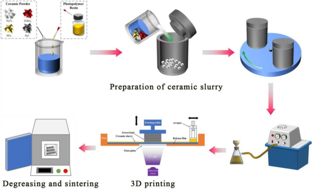
Traditional ceramic cores are formed by hot die-casting or slip-casting, which is suitable for large batches of simple structures. Once complex inner cavities are encountered and small batches are developed, the mold cost is high and the cycle is long. Therefore, surface projection photocuring ceramic 3D printing (VPP) has become an ideal alternative: it is mold-free, has high precision, and can form complex structures in one piece. This also provides an opportunity for ceramic 3D printers to enter the niche field of aerospace ceramic cores.
However, layer-by-layer solidification inherently carries the gene of "interlayer defects". The printed ceramic core is a multi-layer stacked structure, which inevitably leaves interface gaps, particle segregation and local resin enrichment between layers. After sintering, it shows obvious anisotropy in strength and shrinkage - which is fatal for cores that "should be carried in all directions".
0.8% boron carbide counteracts interlayer defects
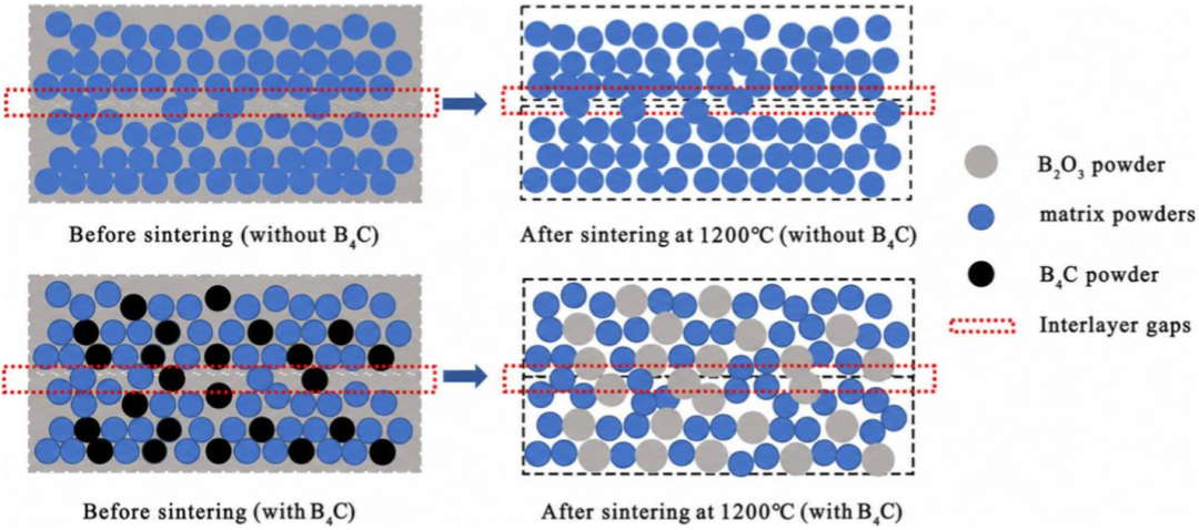
The idea to solve the problem is not complicated: instead of working hard to eliminate inter-layer defects during printing, it is better to add a material that "expands during sintering" to the slurry so that it can actively fill in the gaps during the heat treatment stage. B₄C is exactly that kind of character.
During the sintering process, B₄C particles are oxidized in situ to form B₂O₃, accompanied by a volume expansion of more than 200%: the expansion pushes the surrounding matrix particles to migrate to the interlayer gaps, and B₂O₃ forms a Si–O–B glass phase (liquid phase) at the sintering temperature, bridging the interlayer interface. The equivalent of "layer-by-layer stacking gaps" are welded in situ during sintering without having to change the printing process itself.
More uniform three-axis shrinkage: 2.3% → 0.6%
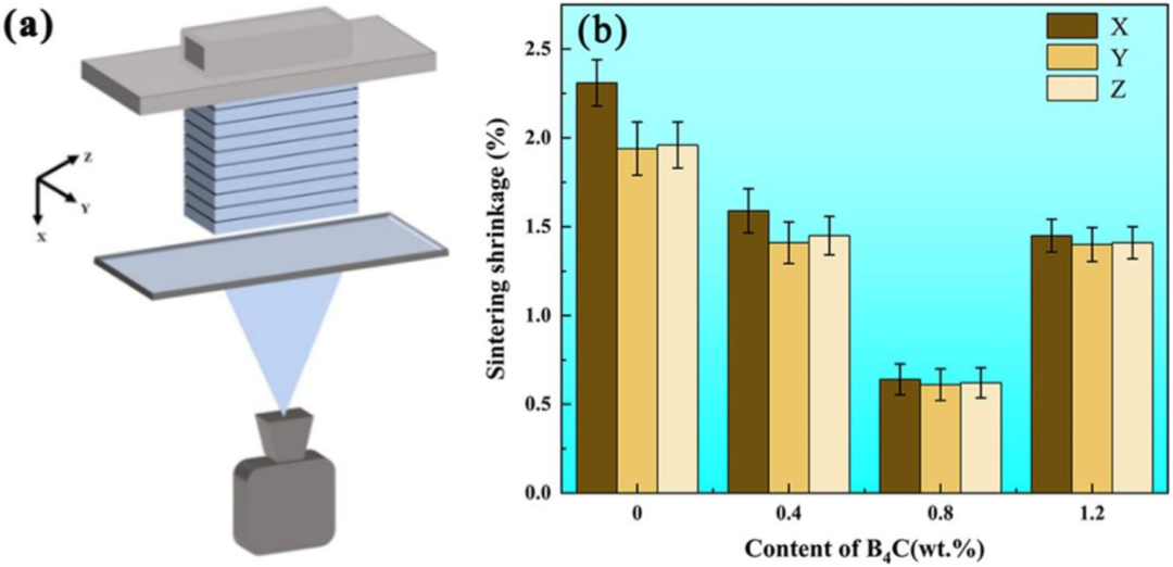
Data speaks volumes. The sintering shrinkage of the undoped sample in the three axes (X/Y/Z) is approximately 2.31%, 1.94%, and 1.96% respectively, with obvious differences in directions; after incorporating 0.8 wt% B₄C, the three-axis shrinkage simultaneously decreases to 0.64%, 0.61%, and 0.62%, almost in equal proportions.
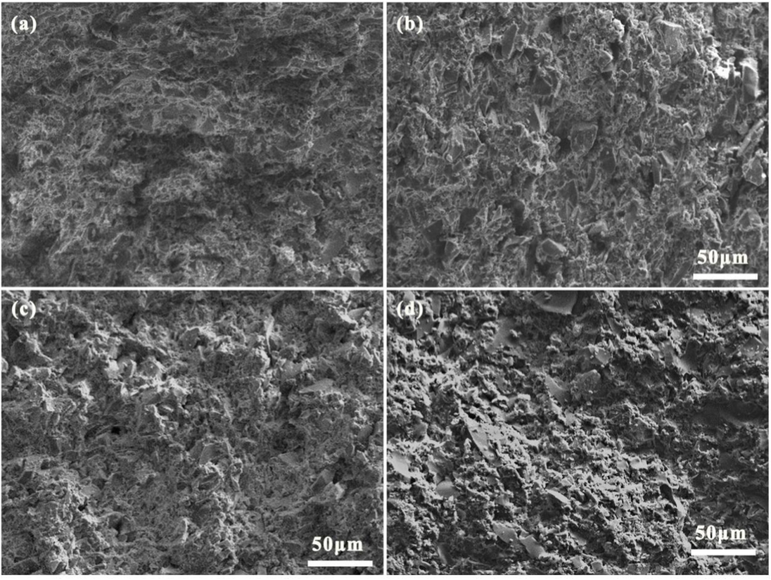
The fracture morphology also confirms this point: the particles in the cross section of the undoped sample are loose, the pores are irregular, and the interlayer transition zone is clearly identifiable; the interlayer interface of the 0.8 wt% sample disappears, the particles are continuously combined, and the interlayer interface is no longer identifiable. The two pieces of evidence, shrinkage rate and morphology, point to the same conclusion—interlayer defects are effectively suppressed.
Directional strength consistency: 0.57 → 0.93
The "directional consistency" of strength is the core indicator of core service. The study uses the ratio of vertical to horizontal bending strength (σV/σH) to quantify: at room temperature, this ratio increases from 0.57 for the undoped sample to 0.89 for the 0.8 wt% sample; at a high temperature of 1540°C, it increases from 0.63 to 0.93, corresponding to horizontal and vertical strengths of 20.4 MPa and 19.0 MPa respectively, and is almost no longer affected by the printing direction.
An interesting "reverse balance" is: after doping with B₄C, the bulk density decreases slightly from 1.473 g/cm³ to 1.420 g/cm³, and the apparent porosity increases from 30.3% to 32.6%. Decreasing density and increasing porosity are bad things for structural parts, but good for ceramic cores - a porosity higher than 30% is conducive to the penetration and reaction of alkali liquid during subsequent core removal.
Chemical compatibility with GH3030 nickel alloy
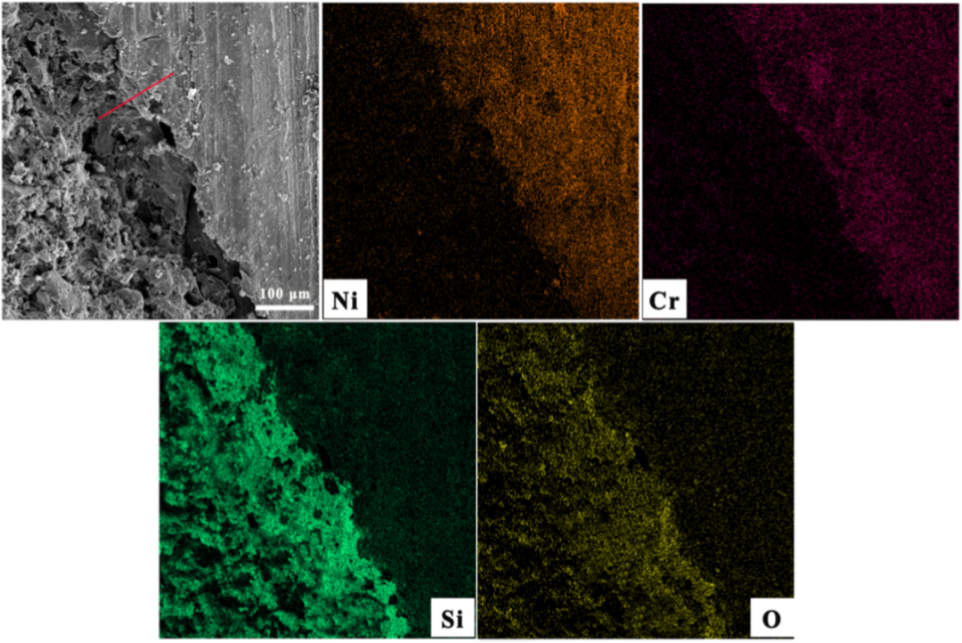
The ceramic core must ultimately "hold the interface" under nickel-based high-temperature alloy casting conditions. The study used GH3030 alloy for actual investment casting. The EDS element distribution showed that Si and O were concentrated on the side of the core, and Ni and Cr were concentrated on the alloy side. The interface was clear and continuous; no obvious reaction layer or new phase was found in the EDS line scan and XRD spectra, indicating that the 0.8 wt% B₄C system has good chemical compatibility under nickel-based casting conditions at 1540°C.
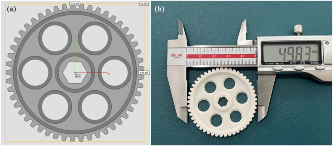
The gear sample further verified the feasibility of the project: the sintered gear-shaped ceramic core has a complete structure, no cracking or collapse in the thin wall, a linear deviation of about 0.3%, and controllable dimensional accuracy.
Three concluding implications
Back to the development of ceramic cores. The change brought about by adding 0.8 wt% B₄C seems to be only a few percentage points, but behind it is actually a change of thinking. Distill it into three points:
First, interlayer anisotropy is not necessarily limited to the “process side”. Light-curing layer-by-layer molding inherently has differences between layers. In the past, it was mostly controlled by repeatedly adjusting process parameters. This study moves the solution to the problem forward to the "slurry end" - only changing the formula, leaving the equipment and process unchanged, the triaxial shrinkage converges from a difference of nearly 3 times to about 0.03, and the strength anisotropy index also drops significantly. When the process reaches the bottleneck, changing the formula variables may save more effort than continuing to adjust the process.
Second, a small amount of dopant can serve as an "interlayer bridging agent." The B₂O₃ generated by the oxidation of B₄C forms a Si–O–B glass phase at the sintering temperature, bridging the interlayer interfaces and eliminating the interlayer boundaries. The fracture morphology also confirms this. This shows that doping is not just about adjusting density or color. If you choose the right system, it can directly repair the microscopic weaknesses left by layer-by-layer printing.
Third, the evaluation of complex ceramic cores depends on the "degree of isotropy" rather than the absolute value of one direction. The most noteworthy thing about the paper is not how high the strength is in a certain direction, but that the shrinkage rate and strength anisotropy in the three directions converge significantly. For blade cores with complex internal cavities, consistent directions mean that demolding and sintering deformation are more predictable.
Reference papers:
Yang H, Yan D, Li S, Lu K, Niu S, Li X, Xu