Applications
Ceramic cores for hollow turbine blades
The overview covers complex cooling passages, core removability, high-temperature stability and dimensional control after casting.
This KUNWU editorial note is based on the supplied technical source. Reported results belong to the described study or sample and are not KUNWU equipment specifications.
The traditional ceramic core preparation process is no longer able to meet the stringent requirements of the new generation of aerospace engines for complex cooling structures. 3D printing technology is reshaping the underlying logic of hollow turbine blade casting with its moldless, high-precision, and complex structure manufacturing capabilities.
In the world of aero engines, temperature equals performance. Every time the gas temperature in front of the turbine increases by 100°C, the engine thrust can increase by about 15%. In order to withstand extreme temperatures above 1,600°C, complex cooling channels must be constructed inside modern turbine blades - this is the significance of the existence of ceramic cores. It is like the "heart bridge" of the blade. It forms a precise inner cavity during the casting process and is eventually chemically dissolved, leaving a hollow cooling channel.
However, traditional ceramic core preparation (injection molding, hot pressing, gel casting) is like using a mold to make ice sculptures - long cycle time, high cost, and difficult to achieve complex three-dimensional structures. When engine designers want more tortuous and finer cooling channels, traditional processes are stretched. This is the perfect time for 3D printing technology to intervene.
Four ceramic-printing technologies
There are currently four main technical routes for 3D printing technology used in ceramic cores, each with its own characteristics:
Photopolymerization: SL/DLP
Stereolithography (SL) and digital light processing (DLP) technologies use a mixed slurry of ceramic powder and photosensitive resin as raw materials, and are cured layer by layer through ultraviolet light. SL uses laser point-by-point scanning, which is extremely precise but slow; DLP uses digital projection to solidify the entire layer at once, greatly improving efficiency.
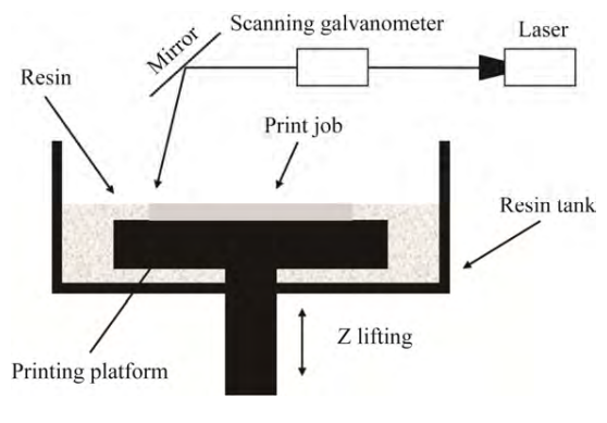
Schematic diagram of stereolithography (SL) technology: a laser beam scans the solidified ceramic slurry layer by layer along a specific path.
Experimental data shows that the silicon-based ceramic core prepared by Li et al. using SL technology has a bending strength of 12.1 MPa after sintering at 1300°C, and a surface roughness as low as 97.2 nm. The aluminum-based ceramic core prepared by Liang et al. through DLP technology achieved a porosity of 35.1% and a bending strength of 20.3 MPa after sintering at 1400°C - this porosity is crucial for subsequent chemical core removal.
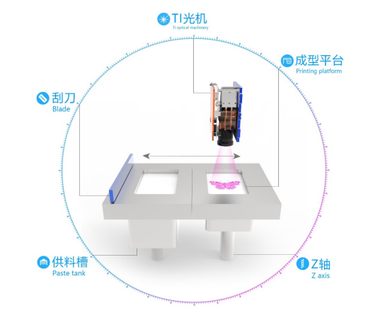
Schematic diagram of digital light processing (DLP) technology: solidifying an entire layer of slurry in one go through digital projection
SLS: rapid forming without separate supports
SLS technology uses ceramic powder as raw material and uses high-energy laser beams to selectively sinter the powder layer. The biggest advantage is that there is no need for a supporting structure, the powder itself can be used as a support, and it is suitable for manufacturing complex structures such as suspended and underturned structures. However, the accuracy is relatively low, and sintered parts usually require subsequent infiltration treatment.
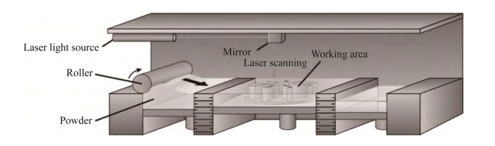
Schematic diagram of selective laser sintering (SLS) technology: after the laser beam sinters the powder layer, the workbench is lowered and new powder is spread
The research by Wen et al. demonstrates the potential of SLS: the silicon-based ceramic core prepared by combining the vacuum infiltration process has a high-temperature creep of only 0.31 mm at 1550°C and a bending strength of 15.04 MPa, which is close to the level of traditional processes.
DIW: flexibility and cost
DIW technology extrudes high-viscosity slurry through a nozzle and stacks it layer by layer. The equipment is low-cost and flexible in molding, but the accuracy is limited by the nozzle diameter (usually 200-500 μm), and the rheology of the slurry is extremely demanding—it must be able to flow during extrusion and maintain shape after deposition.
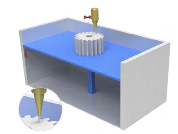
Schematic diagram of direct writing (DIW) technology: the slurry is extruded from a micron-sized nozzle by air pressure or a piston
The dense alumina ceramic prepared by Xie et al. through DIW has a bending strength as high as 380±45 MPa and a theoretical density of 99%, demonstrating the great potential of this technology in the field of dense ceramics.
LEF: low-cost continuous extrusion
LEF technology is similar to DIW, but focuses more on the continuous layered deposition of slurry. It is low-cost and can design complex internal structures, making it a potential candidate for industrial mass production.
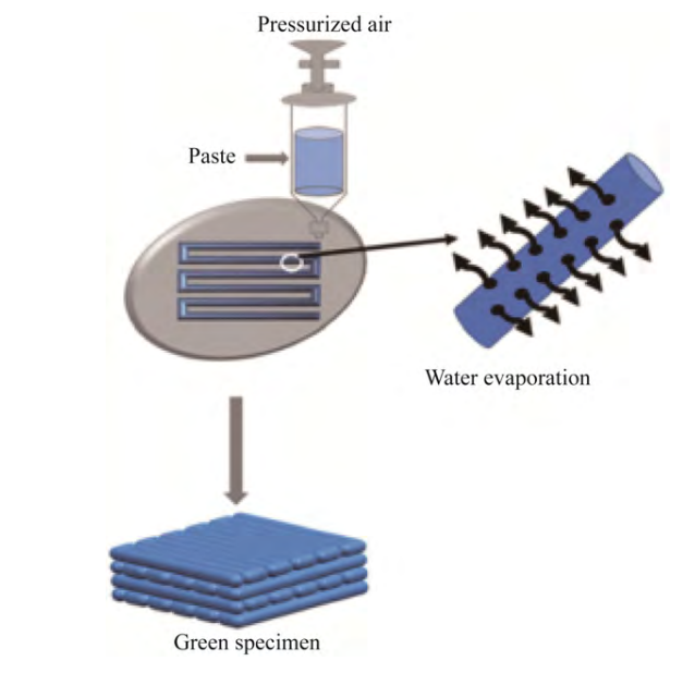
Screeching (LF) technical schematics: continuous stratification of ceramics
Three bottlenecks and ways forward
Despite the bright future, 3D printed ceramic cores still face three core challenges: insufficient printing accuracy, difficulty in balancing mechanical properties and porosity, and anisotropy of structural properties.
Accuracy control: from 1.53 μm to 1.14 μm
Surface roughness directly affects the inner cavity quality of cast blades. Li et al. successfully reduced the surface roughness of the ceramic core from 1.53 μm to 1.14 μm by adding nano-ZrO₂ to fused quartz particles and using nanoparticles to fill the gaps between micron-sized particles, a reduction of 25%.
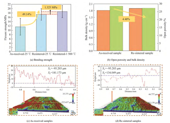
Bending strength, porosity and surface roughness of sintered and re-sintered samples
Balancing strength and porosity
The ceramic core must have sufficient strength to withstand the impact of high-temperature alloy casting, and must have sufficient porosity to ensure subsequent chemical dissolution and core removal. This contradiction is alleviated by optimizing the degreasing and sintering processes: vacuum sintering can reduce shrinkage, and controlling the holding time can adjust grain growth, thereby achieving coordinated optimization of strength and porosity.
Reducing anisotropy
The layer-by-layer stacking nature of 3D printing results in inconsistent performance of ceramic cores within and between layers. By optimizing printing parameters (such as layer thickness, exposure time) and sintering process (such as heating rate, holding time), more uniform mechanical properties in three dimensions can be achieved, and even isotropy can be achieved.
From laboratory to production line
Currently, 3D printed ceramic cores are still dominated by laboratory research and are still far from industrialized mass production. Future development directions include:
- Optimize slurries toward >60 vol% solids, low viscosity and suitable rheology to improve accuracy and sintered density.
- Increase speed and build area through approaches such as multi-laser SL and large-format DLP.
- Study core failure under high temperature and complex stress to establish reliable design rules.
- Integrate different materials, for example ceramics with different thermal expansion, into one core to create functional gradients.
It is foreseeable that when 3D printed ceramic cores are truly industrialized, aerospace engine designers will gain unprecedented design freedom - more complex cooling channels, thinner wall thicknesses, and more optimized airflow organization, which will ultimately push the engine's thrust-to-weight ratio and thermal efficiency to a new level.
Paper citation information: Li Yuan, Li Qiuge, Zhang Hongbo, et al. Research progress on 3D printing and performance control of ceramic cores for hollow blade casting [J]. Casting, 2026, 73(1): 1-10.