Process engineering
Co-sintering metal–ceramic interfaces
The central multi-material challenge is matching shrinkage, chemical compatibility and interfacial stress through the full thermal cycle.
This KUNWU editorial note is based on the supplied technical source. Reported results belong to the described study or sample and are not KUNWU equipment specifications.
Key components in aerospace, deep-sea equipment, metallurgy and other fields often face ultra-high temperatures, strong corrosion, thermal shock, and cyclic loads at the same time—a single material cannot cope with them at all. At this time, multi-material components are needed: different materials are used in different areas to learn from each other's strengths and weaknesses. But how to firmly make metal and ceramics into a whole has always been a problem.
The manufacture of high-energy beam boosters, such as traditional powder bed melting (LPBF), directed energy deposition (DD), has fundamental barriers in printing metal-porcelain materials: the melting point of metals and ceramics, thermal expansion factor (CTE) varies widely, and the process of high-energy local melting is prone to the opening of interfaces, corrosive phase formation and residual stress. Co-combination (co-sintering) of the metal-porcelain system is even more difficult - the two materials have a different contraction rate, and the interface during the sintering process is strong enough to render the whole building useless.
Research published in Advanced Powder Materials (March 2026, DOI: 10.1016/j.apmate.2026.100415) by the State Key Laboratory of Powder Metallurgy of Central South University found a systematic solution: through interface-structure design design), combined with the material extrusion additive manufacturing (MEX) dual-nozzle printing process, achieved the preparation of defect-free NiFe₂O₄-based cermet/CuNi alloy multi-material components, with a bending strength of 367.5 MPa - 125% higher than that of single cermets.
Material selection for inert anodes
The study has a specific application background — aluminium electrolytic inert anode. In the process of electrolytic aluminium, the traditional carbon anode will continuously consume and release CO2, while the inert anode will replace carbon materials with ceramics, which can theoretically achieve zero carbon emissions. However, inert anodes face two competing demands: on the one hand, ceramics are required to provide high temperature resistance, corrosive resistance and high temperature intensity, and on the other hand, metals are required to provide resilience and heat resistance.
The researchers selected two types of materials: NiFe₂O₄-based cermet (Cermet 25, containing 25wt% metal phase) to provide the high-temperature strength and corrosion resistance of the ceramic framework; CuNi alloy (Cu-20Ni) to provide the toughness and electrical/thermal conductivity of the metal phase. The combination of the two can theoretically achieve the functional balance required for an inert anode - but how to make them into a whole is the real problem.
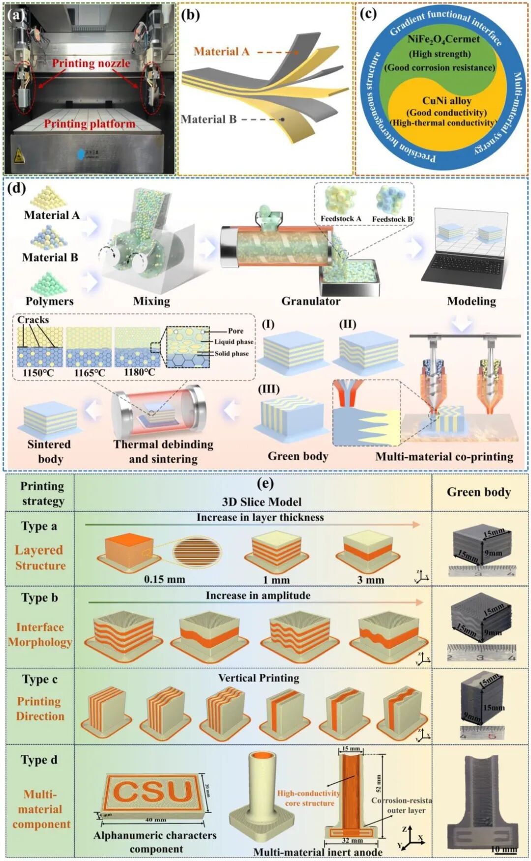
MEX (material extrusion additive manufacturing) is an indirect additive manufacturing route: metal or ceramic powder is mixed with a polymer binder to form a feed, which is melted and extruded through a heated screw, stacked layer by layer into a green body, and then degreased and sintered to obtain the final dense part. Compared with direct melting processes such as laser or electron beam, MEX does not melt the material at the printing temperature - this is particularly critical for metal-ceramic co-printing, fundamentally avoiding thermal stress and interface reaction problems in high-energy beam processes.
Dual-nozzle printing: feedstock rheology and settings
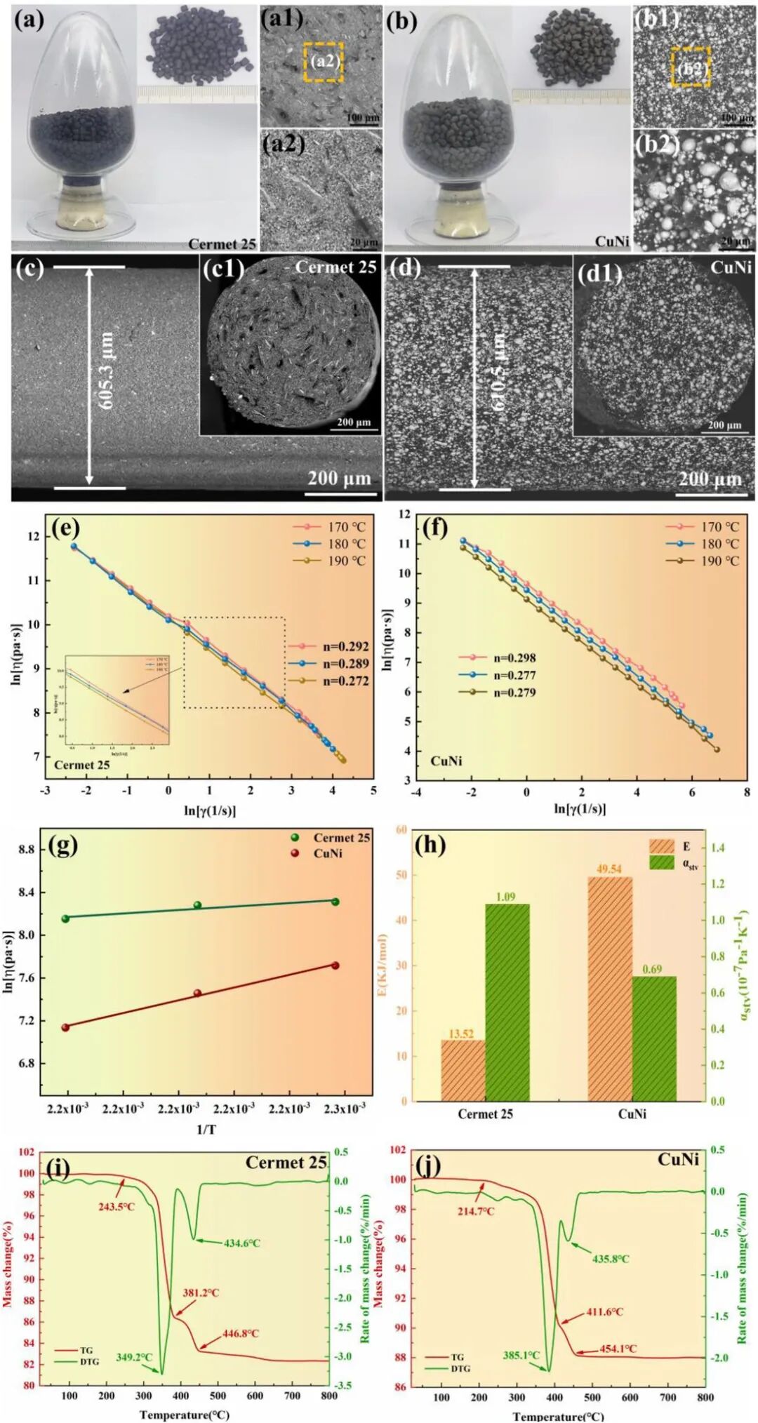
The study uses a dual-nozzle MEX printer to simultaneously extrude Cermet 25 and CuNi feed materials. The two feeds share a POM-based binder system, and the powder loading capacity is 52vol%. Rheological tests showed that both feeds were shear-thinning non-Newtonian fluids. Cermet 25 has the strongest shear thinning property at 190°C (n=0.272), and CuNi has the strongest shear thinning property at 180°C (n=0.277). The viscosity temperature sensitivity of CuNi feed (E=49.54 kJ/mol) is much higher than that of Cermet 25 (E=13.52 kJ/mol), which means that CuNi can optimize printing performance through precise temperature control. The extruded filament diameters of the two feed materials are 605.3µm and 610.5µm respectively, which are highly consistent with the nozzle diameter of 0.6mm, and the printing stability is good.
Three dimensions of interface design
Co-sintering cracking is the biggest obstacle to metal-ceramic multi-material printing. The researchers proposed a three-pronged interface structure design strategy.
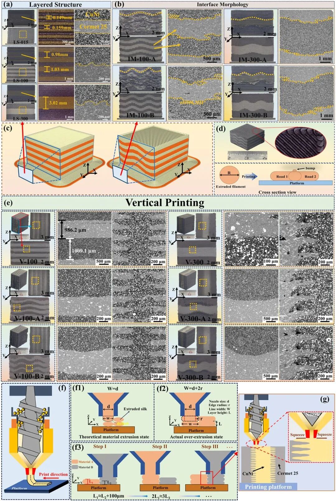
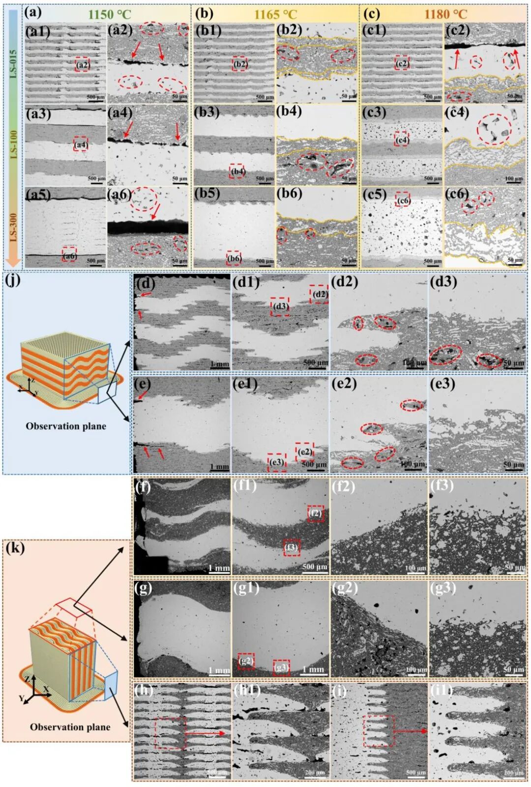
Dimension 1: Metal layer thickness (LS strategy). Three groups are set up - 0.15mm (LS-015), 1mm (LS-100), 3mm (LS-300). The thicker the metal layer, the greater the interface stress caused by thermal mismatch and the more serious the cracking; when thinned to 0.15mm, the thin-layer structure can effectively disperse and relax thermal stress.
Dimension 2: Interface form (IM strategy). Introducing a sinusoidal interface (Type A: y=0.5sin(5πx/3), Type B: y=0.5sin(πx/3)). Compared with the flat interface, the curved interface increases the actual contact area (type A +2.4%, type B +12.8%). More importantly, it converts concentrated transverse tensile stress into a multiaxial stress state to inhibit crack initiation and expansion.
Dimension three: printing direction (vertical printing). Rotate the printing direction 90° to vertical printing, depositing two materials in the same layer at the same time. Due to the over-extrusion and simultaneous expansion of the two materials at the edge of the nozzle, adjacent material flows squeeze each other to fill the pores before solidification, forming a unique jagged interlocking microstructure at the interface - this is a phenomenon unique to the MEX process in vertical printing and cannot be achieved in laser-based processes. The length of the sawtooth is consistent with the line width (approximately 500-560µm), and the thickness is positively related to the layer height (approximately 160-330µm).
Solid–liquid co-sintering: the 1165 °C process window
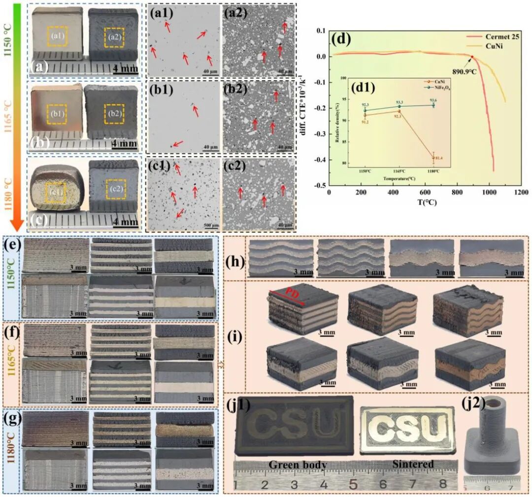
The solidus line of CuNi alloy is about 1158°C and the liquidus line is about 1190°C. The researchers adopted a solid-liquid phase co-sintering (SLPS) strategy: choosing a sintering temperature between the two to partially melt CuNi to form a liquid phase (about 35 vol%), while the ceramic skeleton of Cermet 25 remains solid. The liquid phase greatly reduces the rigidity of the CuNi layer and relaxes thermal stress; at the same time, it serves as a channel for metal phase migration, promoting interdiffusion at the interface to form a transition layer, resulting in micro-mechanical locking. The addition of NiO further enhances the co-sintering effect through the Cu-mediated high-temperature reaction (NiFe₂O₄ → NiO → Cu⋅NiO solid solution).
Comparison of three sintering temperatures: Interface cracks appear in all layered samples at 1150°C (CuNi full solid phase), and the crack width is positively related to the thickness of the metal layer; at 1165°C, the interface cracks completely disappear, the transition layer is dense and defect-free, and is the optimal sintering temperature. The density of the two materials is The density exceeds 92%, and the shrinkage rate in all directions is close to (20-22%); at 1180°C, there is too much CuNi liquid phase (more than 50%), the liquid phase traps gas to form 0.1-0.3mm closed pores, the density drops to about 80%, and the cubic sample is distorted into an ellipsoid due to gravity viscous flow.
125% higher flexural strength and a changed failure mode
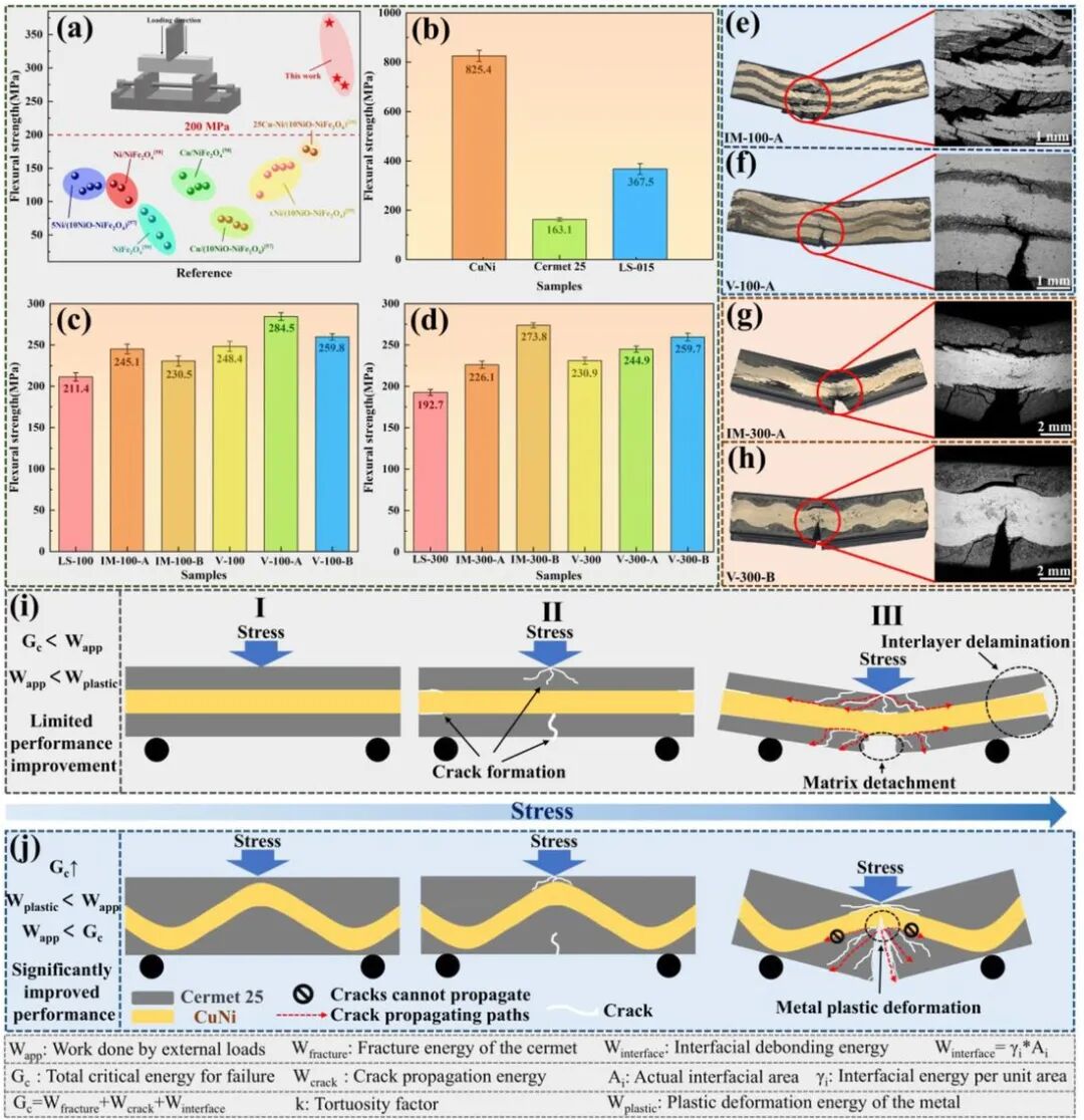
The flexural strength of the LS-015 sample (metal layer thickness 0.15mm) reaches 367.5 MPa, which is 125% higher than the single Cermet 25 (163.1 MPa) and exceeds all reported NiFe₂O₄-based cermet data. The tensile strength also jumped from 28.39 MPa with a 3mm layer thickness to 67.51 MPa with a 0.4mm layer thickness.
The underlying reason for the performance leap lies in a fundamental shift in failure modes. For planar interface structures: limited interface contact area (small Aᵢ) and straight crack path (k≈1), the total fracture energy Gc is small. When the work Wapp done by the external load exceeds Gc but has not yet reached the metal plasticity work Wplastic, the crack expands rapidly along the interface - this is a typical "low-energy, interface-controlled brittle failure".
The zigzag interlocking structure changes this picture. Curved interfaces and vertical printing greatly increase the actual contact area, which directly increases the interface fracture energy; at the same time, the crack is forced to zigzag along a zigzag path, with a zigzag factor k>1, and the crack expansion energy Wcrack increases accordingly. The synergistic effect makes Gc > Wplastic hold - at this time, the external load first triggers the plastic flow of the metal layer (reaching Wplastic). The plastic flow of the metal blunts the crack tip and consumes energy, inhibiting the rapid expansion of the crack along the interface. The load can continue to increase until the ceramic layer finally breaks. This is an essential change from "low-energy interface brittle fracture" to "high-energy metal plasticity-controlled ductile fracture".
Interface architecture as the main design lever
The most important conclusion of this study is the validation of a methodological approach: metal - ceramic multi-material burning and cracking - need not be addressed by "composed formulas" or "dough parameters" - through a systematic interface structure designed to transform stress from the source to a useful multi-axis stress.
Among the three design dimensions, metal layer thinning is the most direct lever (directly affecting the thermal stress amplitude); the curved interface increases the effective contact area and transforms the stress state; vertical printing takes advantage of the unique over-extrusion behavior of the MEX process to naturally form a sawtooth interlocking structure at the interface. The three strategies collaborated with each other and the effects were superimposed, ultimately achieving a 125% increase in strength. This strategy is also effective on complex geometric components - the CSU letter pattern and the functional anode prototype were co-sintered at 1165°C with good geometric fidelity.
Enlightenment for additive manufacturing practitioners: Co-sintering cracking of metal-ceramic multi-material systems is essentially an "interface stress management" problem, not a "material selection" problem. Interface structure design (thickness, shape, printing direction) is a more direct solution than recipe adjustment. The underlying logic of this strategy - converting concentrated stress into multi-axial stress through geometric design and thermal mismatch through liquid phase relaxation - is also of reference value for multi-material additive manufacturing of other metal-ceramic systems (SiC/Al, Al₂O₃/Fe, etc.).
Limitations and outlook
The study is honest about the current limitations: the vertically printed zigzag interlocking structure is effective, but the resolution is limited by the existing nozzle size (0.6mm) and feeding compatibility; in addition, the core electrochemical properties of the inert anode (conductivity, corrosion resistance) are not covered in the article, and this is precisely the key indicator for practicality. Future directions include the development of higher-precision nozzles, customized feeds for multi-material systems, and long-term performance verification in real electrolyzer environments.
Reference papers: Ouyang D, Fan P, Zhang W, Chen M, Zhang K, Xiong H, Kang X, Zhang L, Zhou K, Liu Y, Liu B. Multimaterial 3D printing of high-strength metal-cermet inert anodes for aluminum electrolysis via interface-structure design. Advanced Powder Materials. 2026;5:100415. DOI: 10.1016/j.apmate.2026.100415