Application case
Copper slurry 3D printing: lattices, porous cylinders and five TPMS structures
A supplier case compares three families of complex geometry in the green state. What is already visible after printing, and what must still be validated after debinding and sintering?
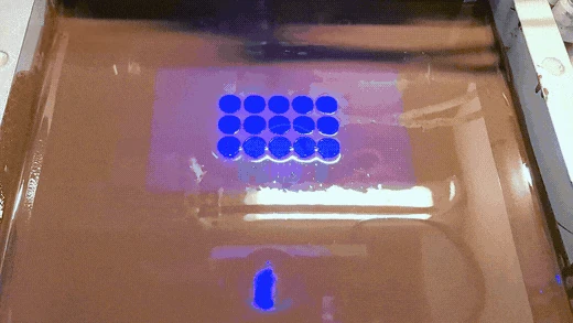
These are supplier demonstration specimens, not KUNWU test results. Every copper specimen shown is an unsintered green body containing binder. Supplier marks were locally removed; reconstructed regions are illustrative and cannot support dimensional or surface measurements. The process image is a still from the supplied animation.
1 · First establish the material state
The case brings together a diagonal-strut lattice, a porous cylinder and five triply periodic minimal surface (TPMS) geometries. Its achievement is geometric: small struts, curved walls and visible pore openings have been formed in copper-containing feedstock. All specimens remain in the printed green state, before densification. A brown or copper-like surface does not establish final metallic density, conductivity or heat-transfer performance.
In slurry photopolymerization, light cures the binder around the powder to hold the shape. Cleaning, binder removal and a qualified sintering route are separate steps. Copper absorption limits the exposure window, heavy particles can settle, and oxidation must be controlled during the thermal route. These constraints make formulation stability and layer bonding as important as the CAD model.
2 · Diagonal struts on a base plate
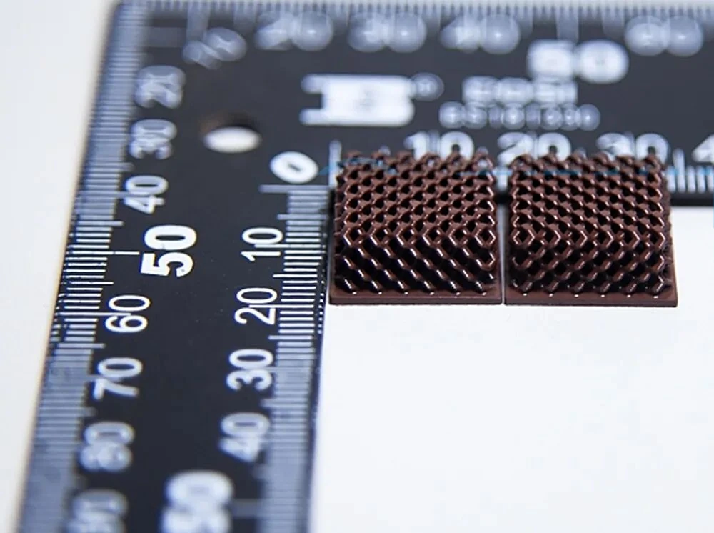
Two intersecting strut directions create a diamond-like lattice above a continuous plate. The useful observation is the transition from slender, interconnected members to a solid base within one printed body. The source photograph also places the specimens next to a ruler, but perspective and the absence of a measurement protocol prevent a reliable tolerance claim.
For a thermal design, the next question is whether the strut-to-base junction survives cleaning and thermal shrinkage. Check local thickening at nodes, unsupported spans, base flatness and cracks after sintering. More surface area alone does not establish a better heat sink; contact resistance, airflow and pressure drop also matter.
3 · Porous cylinders and accessible channels
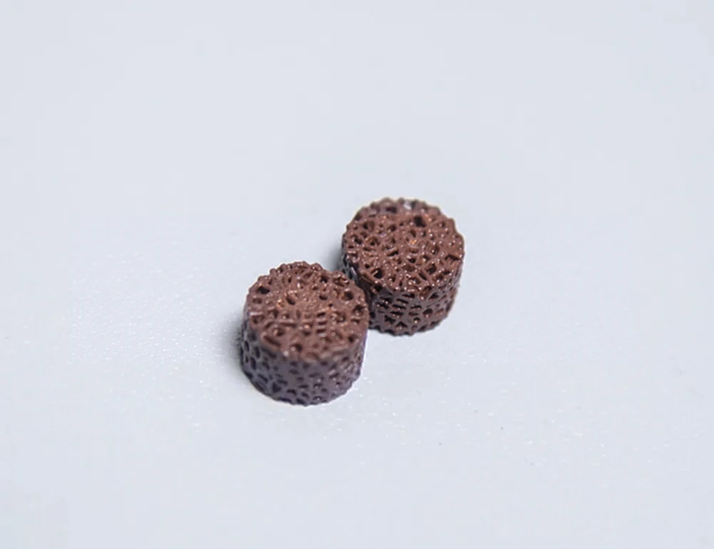
The cylindrical specimens show irregular openings across both the curved outer surface and the end faces. The intended porous network is cut by a cylindrical envelope, so the external contour and internal architecture are designed together. However, a surface photograph cannot confirm that every internal passage is open, clean or connected.
Design the drain and cleaning paths before choosing the smallest pore size. A practical trial should inspect retained slurry, closed openings and fragile walls, then repeat channel checks after sintering. For inaccessible interiors, sectioning or suitable volumetric inspection can complement a flow check; choose the method against the actual component requirements.
4 · What the five TPMS examples actually compare
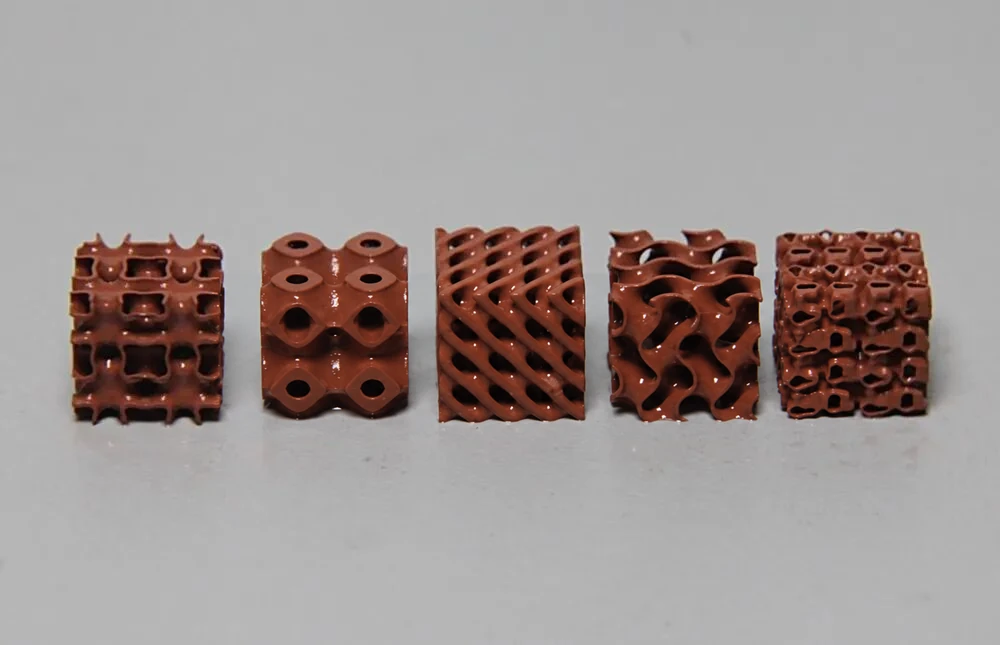
The five examples differ in opening size, opening distribution and the direction in which their curved walls develop. Some expose large rounded openings; others have denser small openings or more strongly undulating surfaces. The source does not provide surface equations, cell dimensions, wall-thickness measurements or specimen-by-specimen topology names. Assigning a familiar TPMS name from a photograph would be guesswork.
A fair comparison for cooling would hold the outer envelope, material state, flow conditions and comparison basis constant. Then measure pressure loss and heat transfer, alongside mass and manufacturability. A visually smooth, connected CAD surface still needs checks for trapped slurry, closed channels and distortion in the manufactured part.
5 · From a printable shape to a qualified copper component
This case does not report final density, oxygen content, electrical or thermal conductivity, leak tightness, thermal cycling or a working cold-plate trial. Those remain separate qualification tasks. Bulk copper reference properties must not be assigned to a porous, binder-containing green body, or assumed for an untested sintered part.
For a KUNWU feasibility discussion, send the CAD file or drawing, finished envelope, minimum passage or wall requirement, intended fluid and temperature, acceptable pressure loss and quantity. State whether the goal is a geometric demonstrator or a functional metal component. Equipment, slurry and post-processing can then be assessed together, with an agreed sample-validation plan before any performance commitment.