Research horizon
Copper lattice by vat photopolymerization
A short note on extending light-based printing to a metal-powder-loaded system, where the main risk shifts to debinding and sintering.
This KUNWU editorial note is based on the supplied technical source. Reported results belong to the described study or sample and are not KUNWU equipment specifications.
Complex metal structures such as lattices, inner cavities, and thin walls are difficult to achieve near-net shape using traditional machining or powder metallurgy; metal additives such as selective laser melting also place high demands on equipment and protective atmosphere. DLP light-curing 3D printing converts metal powder into photosensitive slurry, exposes and solidifies it layer by layer, and then degreases and sinters it. It can achieve near-net shaping of highly complex metal parts. However, the photo-curing of metal slurry itself has outstanding difficulties and is far from comparable to that of oxide ceramics.
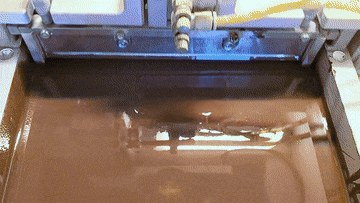
This case uses a copper-based lattice structure as an example to demonstrate the real printing process of DLP light curing and analyze several key difficulties. The sample is printed with ADT Ceram-D-D96.
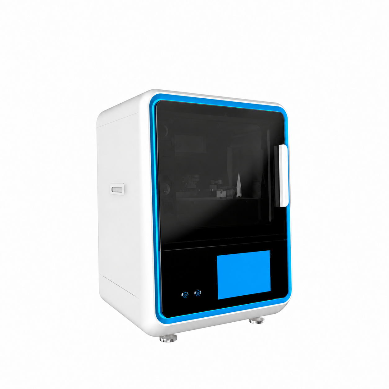
Figure 6 · Desktop DLP printer, ADT Ceram-D-D96.
Specimen architecture
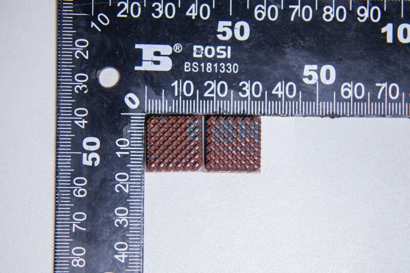
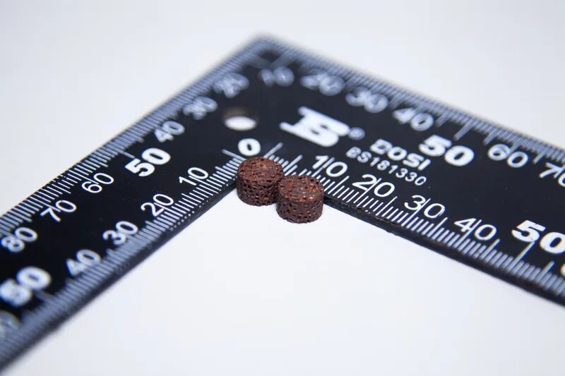
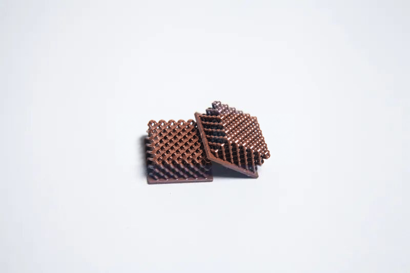
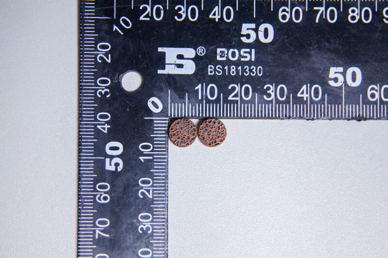
The samples in this case include two types: cubic lattice blocks and cylindrical samples. The cubes are repeatedly arranged by periodic lattice units to form an overall through-hole network, and the surface of the cylindrical sample has a regular grid texture. The unit size, texture period and arrangement density of the two types of samples can all be controlled through the model. The topology can be rewritten by changing the model without re-opening the mold or designing the tooling, which fully reflects the design freedom of copper powder light-curing 3D printing on complex metal parts.
Challenges in copper-powder photopolymerization
The first difficulty with copper powder is slurry stability. The density of copper is much higher than that of alumina, and it settles quickly in resin. To suppress settlement, the slurry viscosity must be increased, but a high viscosity will drag down the bonding between paving materials and layers. The contradiction between high solid content and low viscosity is more acute in copper powder than in oxide ceramics.
The optical level also constitutes the level. Copper powder has strong reflection and scattering of exposure light, making it difficult for photons to penetrate deeply into the slurry. The curing depth is limited, requiring a higher exposure dose, and it is more difficult to control the curing uniformity between deep layers and between layers.
During the sintering stage, copper’s large shrinkage and susceptibility to oxidation superimpose into the final hurdle. The wire shrinkage of copper is obvious, and the thin lattice rods are easy to collapse and warp under shrinkage stress; and copper is easily oxidized at high temperatures and must be sintered in a reducing (H₂/N₂) or vacuum atmosphere. This requirement is obviously stricter than that of oxide ceramics that are inherently oxidation resistant. It is these inherent properties of copper powder that make it more difficult to print with light curing than conventional ceramic systems.
Green-body specimens
The printed green body is cleaned with solvent to remove residual slurry on the surface and then stored in a dry environment. It can be seen in the picture that the sample structure is complete and there are no printing defects such as cracks or layer separation.