Materials research
DLP hydrogels: rebuilding the network for strength and stretch
A research strategy separates shape formation from final mechanical properties: photocrosslinking, hydrophobic reinforcement and controlled cleavage. The result is evaluated in pneumatic soft structures.
Research interpretation based on the supplied article and the cited paper. Numerical details below are attributed to the supplied technical report; the publisher abstract confirms the overall approach. Results concern a specific hydrogel formulation, not a validated material option or guaranteed specification for KUNWU ceramic printers. The diagrams are original KUNWU conceptual illustrations, not experimental images, molecular models or reproduced paper figures. See the cited paper for the original experimental figures.
1 · Print the shape first, develop the properties afterwards
DLP can form cavities, channels and lattices by curing patterned layers. For soft hydrogels, however, rapid shape fixation and large reversible deformation are competing demands. Dense crosslinking can constrain chain motion; long-chain precursors can instead raise viscosity and complicate recoating. The cited work addresses this formulation problem rather than treating optical resolution as the only design variable.
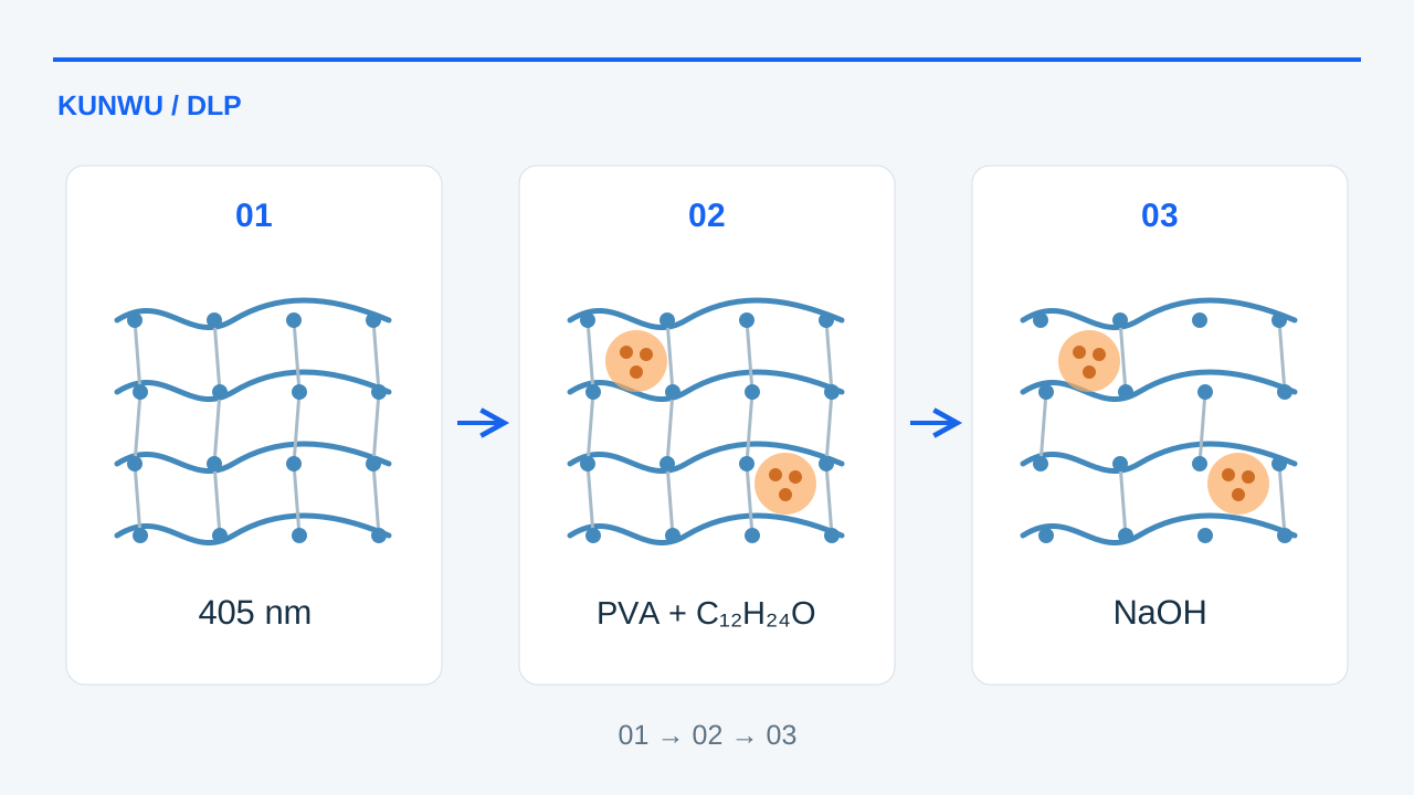
The researchers establish a temporary covalent network during printing, introduce hydrophobic reinforcing domains, then cleave part of the crosslinks. This sequence retains a printable intermediate while allowing a more mobile final network. It is a materials-development route, not a setting that can be enabled on any DLP printer.
2 · Formulation and the printing window
The supplied report describes PVANB, a poly(vinyl alcohol) backbone bearing o-nitrobenzyl groups, at 16 wt% and a number-average molecular weight of 78 kDa. Methacrylated hyaluronic acid (HAMA, 44 kDa, 3 wt%) helps preserve the printed structure. LAP initiates photopolymerization, tartrazine controls light penetration, and urea reduces hydrogen-bond-driven viscosity.
Reported conditions use 405 nm projection, a 60 °C stage, layers of 20–70 μm and exposures of 5–10 s at 50–100 mW/cm². Builds take about 1–2 h in the described examples, followed by 395 nm post-curing at 500 mW/cm². These are study-specific conditions: exposure, thickness, temperature and formulation must be assessed together, and the values are not a ready-to-run recipe for another machine.
3 · Reinforce before partially releasing the network
Light-driven acNB chemistry introduces ester-containing, alkali-cleavable links during network formation. The source describes spectroscopy and model-reaction measurements supporting this mechanism. Those model reactions are separate from the printer exposure conditions and should not be used as machine cure-time specifications.
Acid-catalysed modification with dodecanal adds hydrophobic side groups to PVA. Their association forms physical reinforcing domains in the hydrated matrix. In the source comparison, this step raises tensile strength from 0.7 to 6.3 MPa and Young’s modulus from 1.94 to 8.9 MPa. Reinforcement alone does not deliver the final balance of strength and stretch.
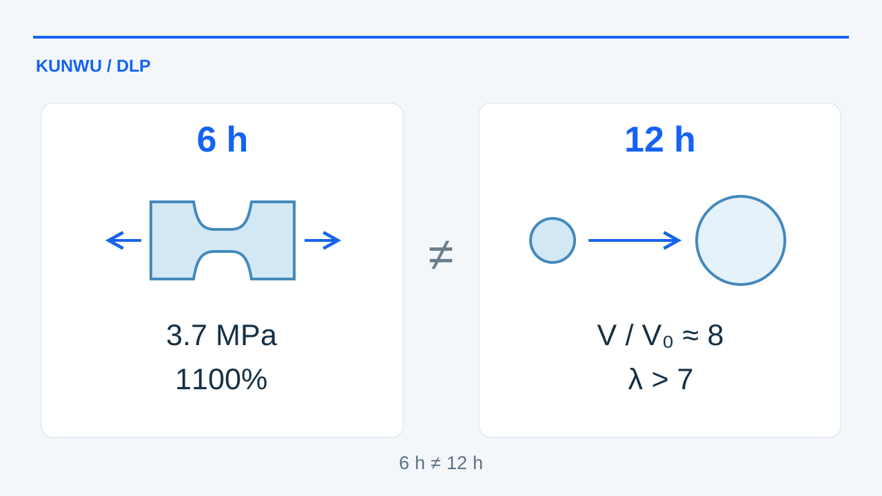
Partial alkaline cleavage then increases chain mobility while the physical domains and entanglements help maintain integrity. The report compares 2, 6, 12 and 24 h treatments in 1.5 M NaOH. Treatment duration matters: the 6 h group is used for the principal mechanical comparison; the more extensible 12 h material is used for pneumatic demonstrators. These groups must remain distinct.
4 · Mechanical gains and dimensional trade-offs
For the 6 h group, the supplied report gives 1100% strain at break and 3.7 MPa tensile strength, compared with 68% and 0.7 MPa initially. Work to fracture and tear energy also increase. The table preserves the intermediate hydrophobic stage rather than incorrectly assigning its peak strength to the reconstructed material. A dash means the supplied summary did not give that value.
The report describes elastic recovery over 100 loading cycles and stability during the reported water-storage observation, not an unlimited fatigue life. Its comparison with 25 published DLP hydrogels and friction benchmarks is useful research context; differences in test conditions prevent treating it as a universal product ranking.
The reported in-plane feature resolution changes from 55 to 37 μm after modification and reconstruction, attributed to shrinkage. This does not mean the projector pixels became smaller, nor does it establish finished-part dimensional accuracy. Dimensional compensation and retention of channel geometry still need verification for each design.
| Property | As printed | Hydrophobic modification | Reconstructed: 6 h |
|---|---|---|---|
| Strain at break | 68% | — | 1100% |
| Tensile strength | 0.7 MPa | 6.3 MPa | 3.7 MPa |
| Work to fracture | 0.27 MJ/m³ | — | 23.4 MJ/m³ |
| Tear energy | 81 J/m² | — | 1150 J/m² |
| Young’s modulus | 1.94 MPa | 8.9 MPa | — |
| Reported in-plane feature resolution | 55 μm | — | 37 μm |
5 · Pneumatic chambers and soft robots
The 12 h treatment group supports the pneumatic devices. In spherical chambers, the report compares volume ratios of 1.9 for the untreated material, 3.0 after hydrophobic modification and about 8 after reconstruction; the last group reaches a maximum stretch ratio above 7. Volume ratio V/V₀ and stretch ratio λ describe different quantities and must not be confused with tensile strain at break.
Constitutive models fitted to tensile data are used to simulate inflation and bending. The examples include printed Pneu-net elements assembled into a three-finger gripper, a monolithic quadruped with separately controlled pneumatic legs, and a worm-like robot with an elongating chamber and two expanding chambers. Their internal channels reduce the need for sacrificial mould cores.
The quadruped demonstrates motion on a wet inclined surface; directional foot friction converts cyclic inflation into displacement. The worm-like device uses sequential expansion and anchoring to move in a liquid-filled tube and transport a 10 g load, with about 0.1 N reported thrust. These are laboratory demonstrations, not evidence of clinical use or an in-vivo-qualified device.
| Demonstrator | Reported result |
|---|---|
| Untreated spherical chamber | V/V₀ = 1.9 |
| Hydrophobically modified chamber | V/V₀ = 3.0 |
| Reconstructed chamber | V/V₀ ≈ 8; λ > 7 |
| Quadruped leg angle | 90° → 140° |
| Worm-like robot load / thrust | 10 g / ≈ 0.1 N |
6 · What this means for a development project
The transferable idea is to design printing and final performance as separate, connected stages. Shape formation, network chemistry, shrinkage and actuation have to be validated together. A ceramic DLP platform and a hydrogel research system share a layerwise optical principle, but not necessarily resin compatibility, thermal control, chemical resistance or cleaning requirements.
The route requires formulation work and wet post-processing, with appropriate laboratory controls for alkali, reagents and waste. Long-term ageing, repeated actuation in the intended environment, batch reproducibility and any biological use require further evidence. For equipment discussions, define the material system and validation plan first; the cited results are not a commercial qualification of a KUNWU printer.
Sources
Original paper · DOI
Zhao L, Cai J, Qian Q, et al. Controlled crosslink cleavage and phase separation enable highly stretchable and strong 3D-printed hydrogel for soft robotics. Nature Communications (2026). Published 13 October 2026.