Process engineering
Layering and cracks in DLP ceramic cores
The connection between formulation, recoating and binder burnout explains why a clean green part may crack later.
This KUNWU editorial note is based on the supplied technical source. Reported results belong to the described study or sample and are not KUNWU equipment specifications.
The ceramic core of aero-engine hollow blades requires extremely high dimensional accuracy and structural integrity. Traditional processes (injection molding, gel injection molding) are difficult to form complex internal cooling channels, and DLP light-curing 3D printing has become a feasible solution. But almost everyone who has used DLP to print ceramic cores has encountered the same problem: the sintered core has an obvious layered structure, cracks are prone to occur between the layers, and the pores are unevenly distributed, eventually causing the core to break or deform during the pouring process.
Many people attribute the reason to the insufficient curing depth of printing parameters, too large layer thickness, and unreasonable sintering system. The collaborative research between the team of Professor Li Jinguo of the Institute of Metal Research, Chinese Academy of Sciences and the team of Professor Paolo Colombo of the University of Padova in Italy found that the real problem lies in the scraping process. The solid content of the slurry directly determines the flow field structure during the scraping process, thereby controlling the formation of the layered structure and the distribution of cracks.
1. Fluid mechanics of the scraping process: the solid content determines the width of the laminar flow zone
Before each layer of DLP printing is formed, there is a spreading process: the scraper sweeps across the surface of the solidified layer at a certain speed to spread the new slurry. This process seems simple, but actually determines the distribution of ceramic particles within the layer.
Laminar flow zone: a hotbed of particle stratification
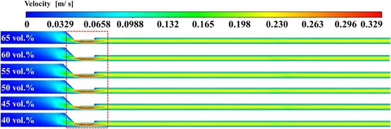
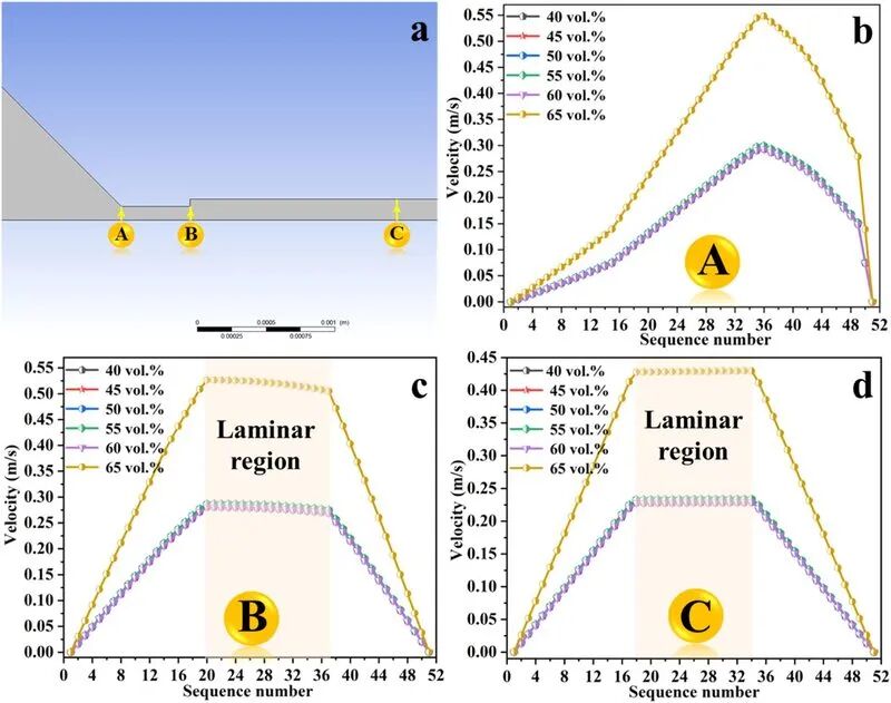
The research team discovered through CFD simulation that during the scraping process, there is a laminar flow zone behind the scraper. In this area, the slurry flows smoothly, the velocity gradient is small, and particles of different sizes have enough time to settle and segregate.
Key findings: As the solid content of the slurry increases from 45 vol% to 65 vol%, the width of the laminar flow zone narrows significantly. The higher the solid content, the greater the viscosity of the slurry, the stronger the flow resistance, the laminar flow zone is compressed, the residence time of the slurry behind the scraper is shortened, and the particles have no time to significantly segregate.
Experimental verification: from simulation to actual measurement
The study used fused silica/ZrO2/Al2O3 ternary system slurry (fused silica 76 wt%, D50=20 μm; ZrO2 20 wt%, D50=10 nm; Al2O3 4 wt%, D50=10 μm) with solid content from 45 to 65 vol%.
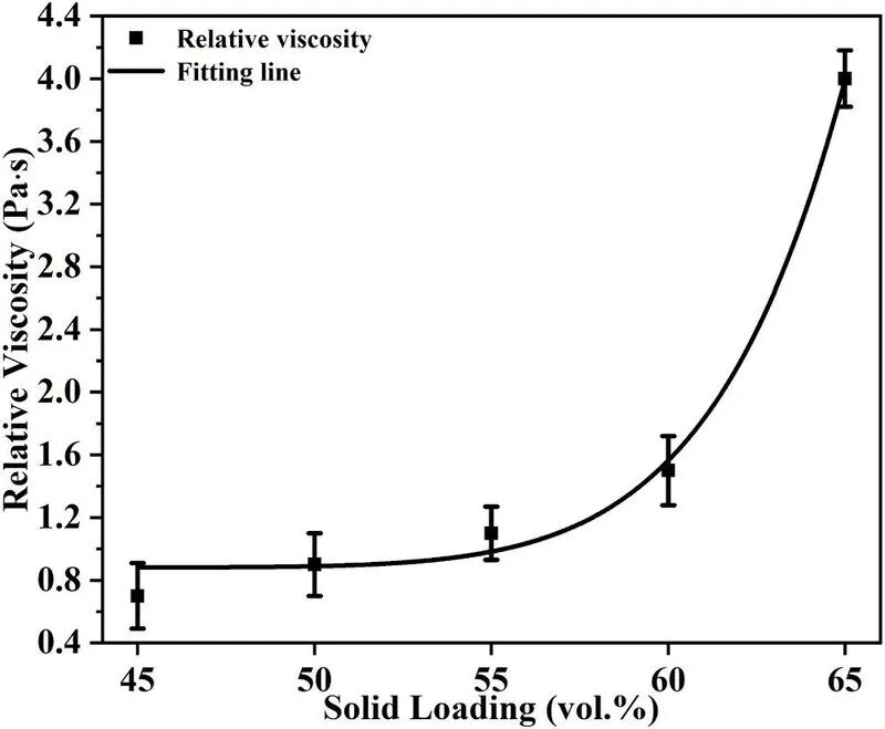
The viscosity test shows that the slurry exhibits near-Newtonian fluid behavior in the range of 45 to 60 vol%, and the viscosity is moderate at the actual scraper shear rate of 200 s-1; at 65 vol%, the viscosity increases sharply, and shear thickening behavior occurs. This means that 65 vol% slurry requires greater scraping force in actual printing, otherwise the layer will be uneven.
2. Microstructural evidence: how solid content rewrites layered structure
SEM and EPMA analysis provide the most intuitive evidence.
Low solids content: significant lamellar segregation
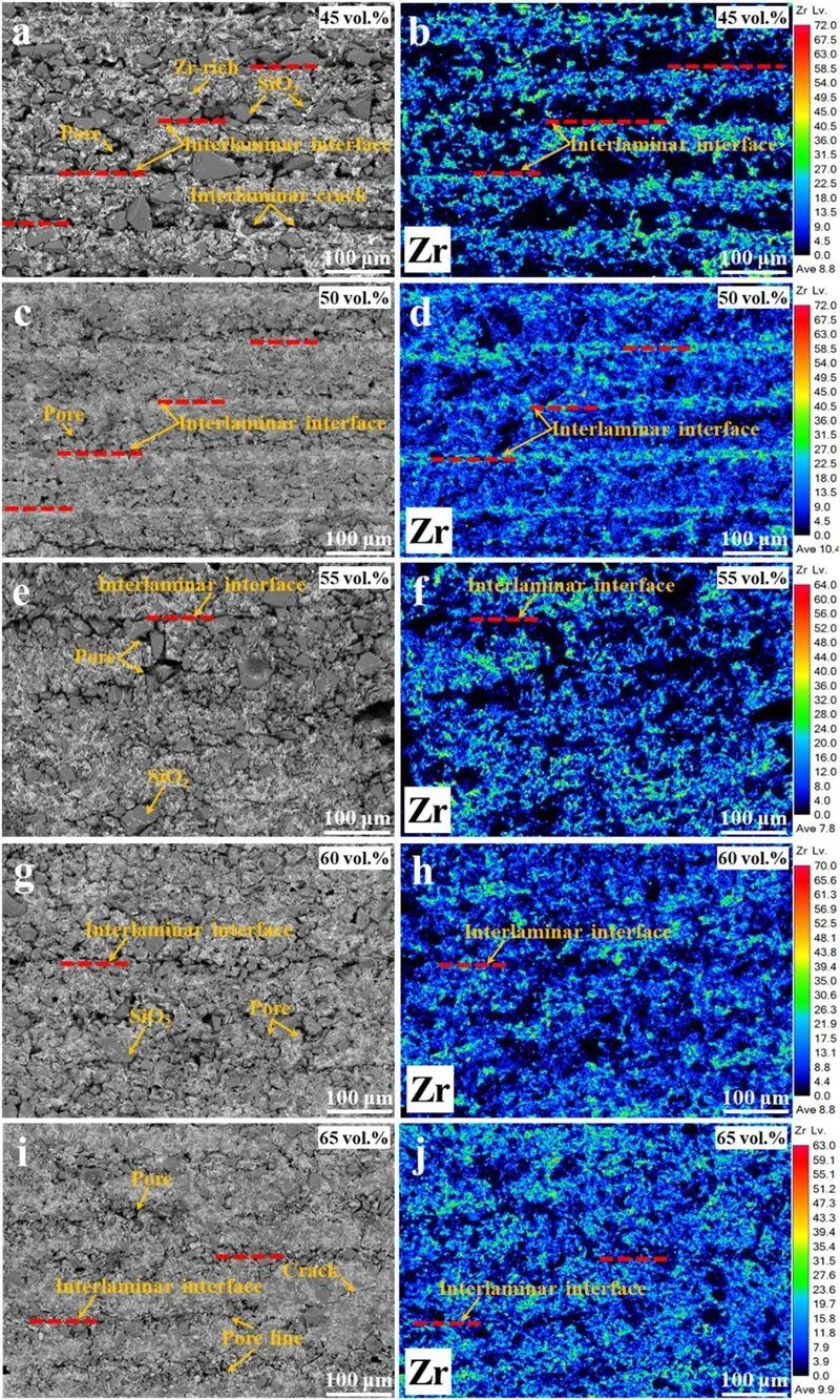
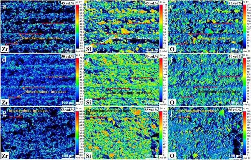
After the 45 vol% sample was sintered at 1200°C, the SEM image showed an obvious layered structure: large fused silica particles were enriched within the layer, and ZrO2 nanoparticles were enriched at the interface between layers. EPMA element distribution confirms that Zr element is enriched at the interface between layers, forming an obvious element gradient line. This elemental segregation results from the settling of large particles to the bottom of the layer during the scraping process, while nanoparticles are carried to the top of the layer.
High solid content: the lamellar structure disappears
When the solid content is increased to 60 vol%, the layered structure weakens significantly; the lamellar interface is almost invisible in the 65 vol% sample, and ZrO2 nanoparticles are evenly distributed in the fused quartz matrix. EPMA results show that the Zr element distribution tends to be uniform and is no longer enriched at the interface between layers.
Conclusion: Increasing the solid content can eliminate lamellar segregation and achieve homogenization of the microstructure.
3. Change of crack mode: from longitudinal cracks to interlaminar cracks
The layered structure is not only a characteristic of the microstructure, but also directly determines the initiation location and propagation path of cracks.
Low solid content: longitudinal through cracks
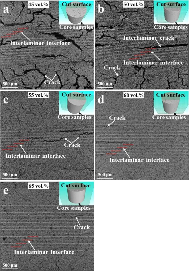
Obvious longitudinal cracks appeared after sintering in the 45~50 vol% sample, penetrating multiple printing layers along the thickness direction. This crack originates from the thermal expansion mismatch between the ZrO2-enriched zone at the interlayer interface and the fused silica matrix within the layer: During the sintering process, ZrO2 undergoes phase change (t→m) accompanied by volume expansion, which generates tensile stress at the interface, causing cracks to initiate and expand vertically along the interlayer.
High solid content: large pores within layers + cracks between layers
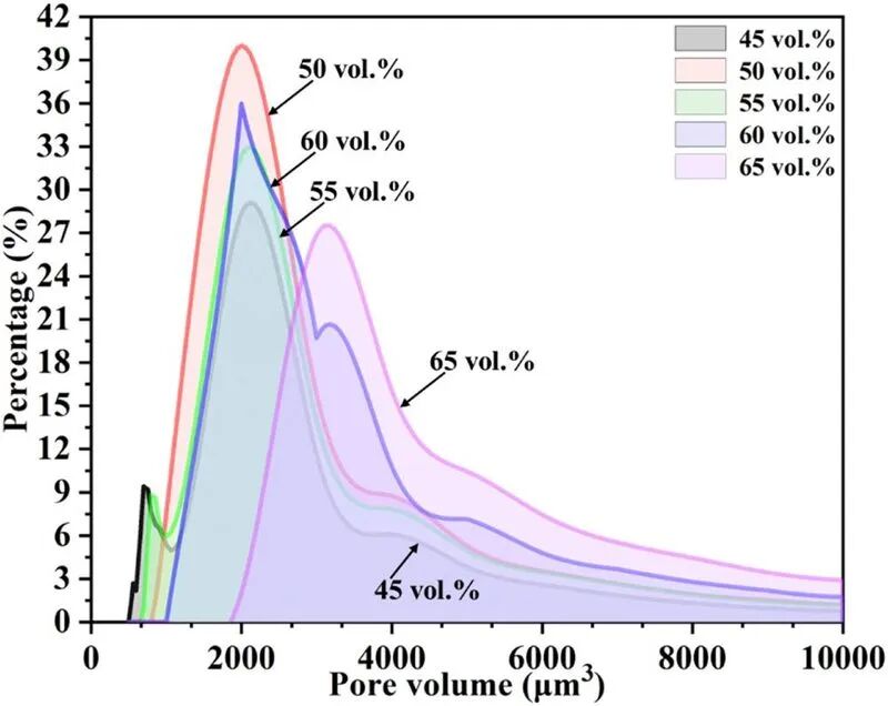
The longitudinal cracks of the 60~65 vol% sample disappeared and were replaced by intra-layer macropores and inter-layer micro-cracks. This is because particles in high-solid content slurries are packed more tightly, the interface between layers disappears, and cracks cannot propagate along the interface; however, due to the high viscosity of the slurry, bubbles are difficult to discharge, forming isolated large pores in the layer.
Trade-off: High solids content eliminates longitudinal through-cracking but introduces new defect forms (large pores within the layer). This needs to be solved by adding defoaming agents to the slurry formula or optimizing the deaeration process.
4. Performance data: global trade-off between porosity, strength and shrinkage
Changes in microstructure are ultimately reflected in macroscopic properties.
Open porosity
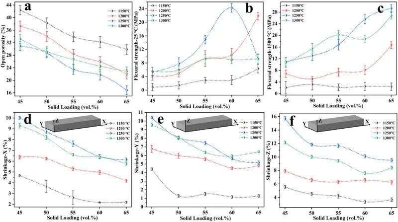
With the increase in solid content from 45 to 65 vol per cent, the opening rate fell from about 35 per cent to about 25 per cent. High solid content means that particles accumulate more tightly and become more dense when burned.
Bending strength
The room temperature flexural strength increases with the increase of solid content: 45 vol% is about 8 MPa, and 60 vol% reaches 15 MPa. However, the 1500°C high-temperature strength test shows that the impact of solid content on high-temperature strength is not as significant as room temperature, and is mainly controlled by the ZrSiO4 in-situ synthesis reaction.
Sintering shrinkage
The sintering shrinkage of low solid content samples shows obvious anisotropy: the shrinkage in the Z direction (layer thickness direction) is greater than the X/Y direction. This is because the ZrO2-rich area at the interlayer interface has high sintering activity and large shrinkage driving force. The anisotropy of samples with high solid content weakens, and the shrinkage rates in the three directions tend to be consistent.
5. Engineering Enlightenment: Optimizing solid content is not as high as possible
This research provides a clear engineering guidance framework:
Solid content 45~50 vol%: low viscosity, good fluidity, suitable for precision molding of complex structures; however, severe layer segregation and high risk of longitudinal cracks, suitable for application scenarios that do not require high microstructure uniformity.
Solid content 55~60 vol%: The layered structure begins to weaken, the overall performance is the best, and it is suitable for most ceramic core applications.
Solid content 60~65 vol%: The lamellar structure disappears, and the density and strength are optimal; however, the slurry has high viscosity, which requires optimization of the scraping system and deaeration process, making it suitable for key components with extremely high strength requirements.
Core conclusion: Solid content is the first control parameter of DLP ceramic printing microstructure, which is more fundamental than printing parameters and sintering system. Optimizing the solid content can fundamentally solve the problem of layered structure and cracks than adjusting the solidification depth, layer thickness, and sintering curve.
Conclusion
This study by the Institute of Metal Research, Chinese Academy of Sciences and the University of Padua reveals the hydrodynamic nature of the layered structure of DLP ceramic printing: the width of the laminar flow zone during the scraping process is determined by the solid content of the slurry. The narrower the laminar flow zone, the weaker the particle segregation, and the less obvious the layered structure. Increasing the solid content from 45 vol% to 65 vol% can systematically eliminate interlayer element segregation, improve pore distribution, increase density and strength, and at the same time change the crack pattern from longitudinal through cracks to intra-layer macropores. For key applications such as aerospace engine hollow blade ceramic cores, it is recommended that the solid content be controlled in the range of 55~60 vol% to achieve a balance between microstructure uniformity and process operability.
References
[1] Q. Li, J. Liang, L. Biasetto, Y. Zhou, J. Li, P. Colombo, "Strategy for optimizing the microstructure of 3D printed ceramic cores: Slurry solid loading and flow," Journal of the European Ceramic Society, vol. 46, 118275, 2026. DOI: 10.1016/j.jeurceramsoc.2026.118275