Catalysis and petrochemicals
3D-printed monolith geometry: channels, porosity and pressure drop
Connecting open area, flow path, wall thickness and accessible surface when designing a ceramic catalyst support.
A KUNWU engineering guide based on open scientific sources. Material, geometry and processing must be validated with the real formulation, active phase and operating environment. Illustrations show design directions and are not results from the cited studies.
Why a honeycomb is only a starting point
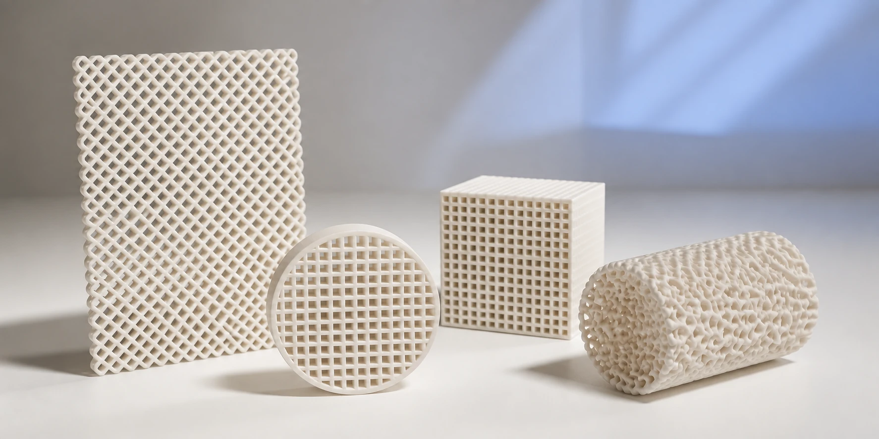
Straight parallel channels provide familiar packing and relatively simple analysis, but may limit transverse mixing. Crossed lattices, staggered layers, TPMS structures and branching channels create different flow paths. Their value cannot be judged by surface area alone because residence time, mass transfer, velocity distribution and fouling risk change together.
Five inputs for the first CAD iteration
Fix the external envelope, minimum clear channel, wall thickness, open frontal area and monolith length. Then define channel direction, turns and access for cleaning or coating. Every feature must remain printable in the green body and land within tolerance after shrinkage.
Mass transfer always has a cost
A classic robocast-monolith study found that geometries without line-of-sight flow could increase mass transfer while also causing a large pressure-drop penalty. A more open geometry delivered a smaller transfer gain with a more moderate resistance increase. These are not design coefficients for a new reactor; they illustrate the trade-off between reagent access and pumping energy.
Macro- and microporosity are created at different levels
The printer establishes part-scale channels and lattices. Specific surface area and fine porosity depend on powder, binder, sintering, pore formers and any later coating. A hierarchical architecture connects these scales but requires separate control of strength, shrinkage, impregnation and active-phase distribution.
A minimum validation plan
Compare at least two geometries at the same external envelope and composition. Measure post-sintering dimensions, open porosity, handling strength, pressure drop across the full flow range and coating distribution. Begin catalytic testing only after hydrodynamic and thermomechanical screening of the specimen.
Compare geometries on the same basis
For a useful trial, hold reactor envelope, catalyst chemistry, loading method, temperature and feed composition constant. Report superficial velocity as well as volumetric flow. Measure the empty support and coated support separately: a coating changes channel clearance, roughness and accessible pore volume.
Connect geometry to measurable transport
Use hydraulic diameter dh = 4A/P, where A is flow area and P the wetted perimeter, and Reynolds number Re = ρudh/μ. Record the definitions of area and velocity; a lattice and a straight channel do not necessarily share the same characteristic length. Measure pressure drop across the insert, excluding connectors, and use inlet/outlet tracer signals to identify bypass and dispersion.
A decision gate before scaling
A trial passes only if it meets the agreed conversion or selectivity, pressure-drop limit and mechanical requirements together. Inspect channels after coating and thermal cycling, weigh coating loss after washing, and repeat the run to distinguish real improvement from sample variation. These are KUNWU engineering recommendations, not numerical results from the cited papers.