Application case
SiC radiant panels: printing a staggered through-hole array
A manufacturing case follows slurry printing, a perforated silicon-carbide plate and a local flame demonstration. What does the geometry enable, and what still needs testing?
This is an editorial account of a supplied manufacturing demonstration, not a KUNWU test report or a qualified burner specification. No calibrated temperature, efficiency, pressure-drop or service-life results are supplied. Supplier logos were removed only within small local regions; reconstructed texture is illustrative, not original measurement evidence. The printing animation is presented as a still frame.
1 · Why combine SiC with a perforated plate?
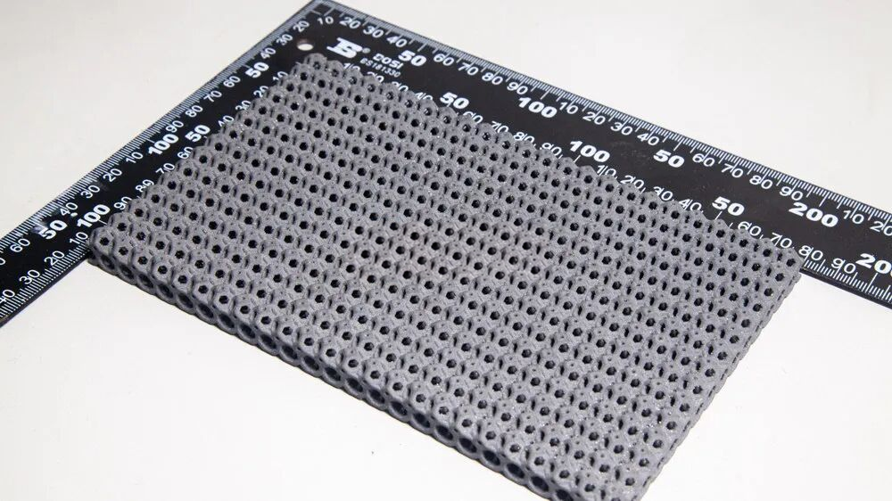
Silicon carbide is considered for high-temperature heating components because of its thermal and mechanical properties. In this case, the material is shaped into a rectangular plate with staggered circular holes. The design creates repeated flow passages and heated surfaces in one component; the performance depends on both the ceramic and its geometry.
A large array of holes would otherwise require repeated machining operations. Additive manufacturing defines the passages in the digital model and builds them with the surrounding walls. This changes the manufacturing route, but does not remove the need to assess slurry behaviour, post-processing, shrinkage and dimensional inspection.
2 · From a slurry layer to a repeated channel pattern
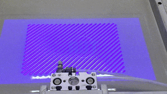
The source animation shows a blade spreading slurry across the build area, followed by layer curing. Repetition builds the plate and its hole array. The clip illustrates layer formation; it is not a complete record of cleaning, debinding or sintering, and it does not establish the exposure settings or final ceramic composition.
The finished plate is shown with staggered through-holes and repeated webs between adjacent passages. The source supplies no dimensioned drawing, hole pitch, wall tolerance or open-area ratio. Dimensions and production-rate figures from other SiC products should therefore not be assigned to this specimen.
3 · What the flame demonstration shows
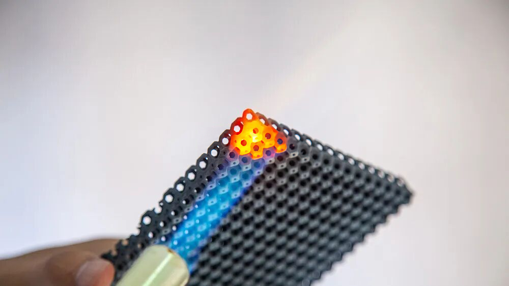
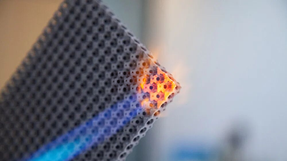
A flame is directed at one corner of the perforated plate. The photographs show a blue flame and a locally glowing orange-yellow region. This is useful visual evidence of the demonstration setup and local heating. The emission colour alone is not a calibrated temperature measurement: exposure, surface condition and illumination all affect the image.
The source interprets the heated SiC as a radiating surface. It does not report spectral emissivity, heat-flux mapping, fuel consumption, thermal cycling or a controlled comparison with a conventional panel. The case therefore supports further application assessment, not a claim of proven heating efficiency, uniform temperature or guaranteed flame resistance over a specified lifetime.
4 · Turn the concept into a testable design
An engineering assessment should first define the heat source, atmosphere, operating temperature, heating and cooling rates, mounting arrangement and allowable pressure drop. Hole diameter, pitch, plate thickness and edge geometry can then be evaluated together. Narrower passages and thinner webs change flow and thermal gradients as well as manufacturability; they should not be optimized independently.
A representative trial should document the material route, finished dimensions and channel openness, followed by application-specific temperature mapping and thermal-cycle inspection. For a KUNWU project review, provide a drawing or target dimensions, the intended heating conditions and the required quantity. Equipment selection and sample validation can then be discussed against those requirements.