Process engineering
Solid loading and layering in ceramic cores
Higher powder loading can reduce shrinkage while changing viscosity, layer recoating and the risk of interlayer defects.
This KUNWU editorial note is based on the supplied technical source. Reported results belong to the described study or sample and are not KUNWU equipment specifications.
1. The blades need to be resistant to high temperatures. First ask the core if you agree.
The thrust-to-weight ratio of a turbofan engine depends largely on the temperature in front of the turbine. Every time the temperature goes up, the blades must withstand a more demanding heat load, so the inner cavity cooling channel has evolved from a single-layer simple channel to a multi-layer, multi-channel complex cooling system. To "carve" such a set of labyrinths inside the casting, traditional hot-press injection molding requires repeated assembly of multiple sets of molds. The cost is high, the cycle is long, the matching accuracy is difficult to guarantee, and it is almost impossible to create truly complex configurations.
The preparation of ceramic core has therefore become an unavoidable joint in blade manufacturing. The so-called ceramic core is the "negative space" that is pre-embedded in the mold cavity during investment casting and can be dissolved after molding: it first occupies the position where the cooling channel should be, and after the single crystal blades are solidified, the core is dissolved with alkali solution, leaving a ventilation channel. The accuracy, density and thermal stability of the core directly determine whether the blade can be formed in one go.
For this complex configuration, ceramic 3D printing gives a new solution. Slurry is solidified, layered and stacked under ultraviolet light, cores are no longer subject to moulds, and cooling corridors can go around several bends. But piles of layers also create problems: layers of interfaces are formed between each layer, particles are not evenly distributed within and between layers, and macros are presented as "layered structures". This structure allows the pore to be distributed in different directions of the opposite sex, and it is also prone to cracks when burned, making it the most variable of the core mass.
2. Where does the layered structure come from: the "layered game" during paving
To understand the layered structure, you must first understand how the slurry is laid. When ceramic 3D printing, a scraper spreads the slurry into a thin layer on the platform, and then exposes and solidifies it. This may seem like an ordinary pile, but there is something special inside: the particles are of different sizes. Small particles are more likely to follow the slurry, while larger particles are easier to settle in the layer.
Ceramic slurry with ternary particle size matching is used (76 wt% fused silica D50=20μm, 20 wt% nano ZrO₂ D50=10nm, 4 wt% Al₂O₃ D50=10μm), and the particle size ranges from micron to nanometer. During paving, small particles tend to gather near the interface of the slurry layer, and large particles tend to sink within the layer. Therefore, each time a layer is solidified, a particle gradient is cured in which the interface is finer and the layer is coarser. When layers are stacked up like this, a layered structure is inevitable.
What role does the solid content play? The key lies in the flow state of the slurry. Experiments show that when the solid content is less than 60 vol%, the slurry is almost Newtonian, and the viscosity changes little with the shear rate; once it exceeds 60 vol%, the steric hindrance between particles increases significantly, and the viscosity rises sharply—from about 0.6 Pa·s at 40 vol% to more than 4 Pa·s at 65 vol%, and the slurry also obviously turns to non-Newtonian shear thickening behavior.
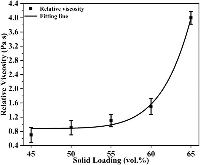
Using computational fluid dynamics (CFD) to simulate the flow field near the scraper, the rules are clearer: the higher the solid content, the more viscous the slurry, the narrower the laminar flow zone of the slurry in the middle section during paving, and the shorter the flow time. The laminar flow zone is narrowed, the slurry layer is mixed more evenly, and the separation of particles within the layer is suppressed - this is the underlying logic of using the "solid content" knob to adjust the strength of the layered structure.
3. Porosity and cracks: "change" with solid content
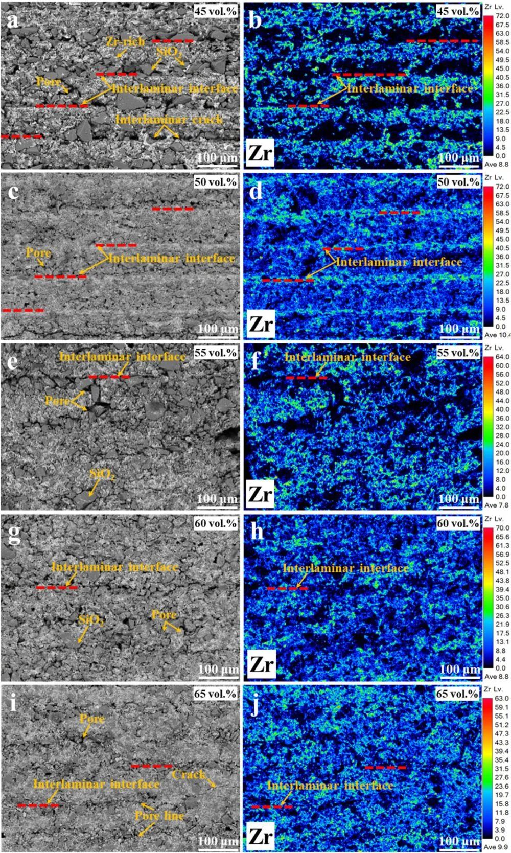
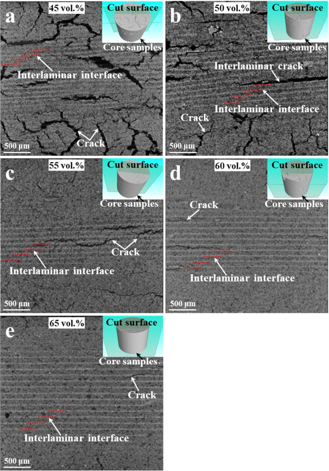
The direct consequence of the layered structure is the evolution of pores and cracks. After sintering the samples with different solid contents one by one, use SEM to observe the microscopic morphology of their side surfaces, and you can clearly see the regular changes.
For samples with low solid content (such as 45 vol%), the layered interface is loose, with a large number of pores of different sizes distributed, and the layers are relatively dense; the sintering shrinkage is large, and longitudinal cracks are prone to initiate at the interface. As the solid content rises to 50 or 55 vol%, the layered interface gradually becomes denser and the number of pores is significantly reduced. However, there are still "pore lines" between the layers, which are traces left by the interface where small particles are enriched.
As the solid content continues to increase, the longitudinal cracks gradually transform into interlayer cracks, and the pore lines originally distributed along the layers also transform into large pores within the layers. When the solid content exceeds 60 vol%, the interlayer interface has been "filled in" by the solid content, and crack generation is effectively suppressed from the source. This exactly echoes the CFD prediction that higher solid content compacts the interlayer interface and reduces layered defects.
4. Performance implementation: balance of porosity, strength and shrinkage
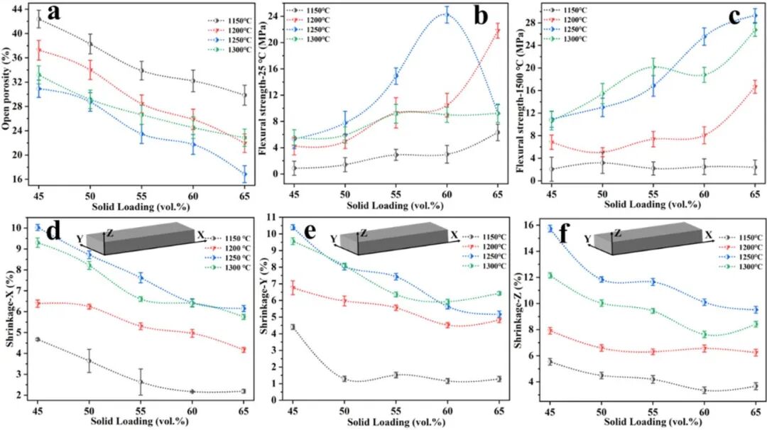
After the microstructure has been straightened out, it ultimately depends on whether the macroscopic properties can satisfy precision casting. Samples with different solid contents were sintered at 1150, 1200, 1250, and 1300°C, and the porosity, flexural strength, and sintering shrinkage were systematically measured. The conclusions were highly consistent with the microscopic observations.
The open porosity decreases with the increase of solid content and decreases significantly with the increase of sintering temperature. The most eye-catching group: 65 vol% solid content + 1250°C sintering, the porosity drops to about 18%, which is the lowest in the field; the other solid content and temperature combinations are basically above 20%.
| Solids (vol%) | Layer interface | Pore/crack features | Open porosity near 1250 °C |
|---|---|---|---|
| 45 | Loose, porous | Many interface pores; longitudinal cracks | >20% |
| 50–55 | Increasingly dense | Fewer pores, residual interlayer pore lines | >20% |
| 60–65 | Dense, solid | No longitudinal cracks; larger intralayer pores | Down to ~18% |
Table 1 · Effects of solids loading on layer interfaces, pores, cracks and open porosity.
Flexural strength and shrinkage also have a "sweet spot". When the solid content exceeds 55 vol% and the sintering temperature is higher than 1200°C, the flexural strength is sufficient to meet the requirements of precision casting; when the solid content is ≥60 vol% and the sintering temperature is ≤1200°C, the porosity is ≥28% and the flexural strength is about 15 MPa, which is a friendly ratio for the dissolution process. Conversely, when the solid content is lower than 55 vol%, or the sintering temperature is higher than 1250°C, the sintering shrinkage exceeds 7%, which is unacceptable for investment casting.
Also worth noting is anisotropy. Because of the existence of the layered structure, the sintering shrinkage of the printing layer in the Z direction is about 50% higher than that in the other two directions - this means that the shrinkage in each direction after demoulding is not equal. This layer direction difference must be reserved when designing the core size, otherwise the finished product will easily exceed tolerances.
More interesting is the double-sided nature of the layer structure. Data show that in samples with solid content exceeding 60 vol per cent, the resistance of 1300 °C to high temperature burning specimens is significantly lower than that of 1250 °C. The paper analysis noted that this anomaly may result from the loss of layered structures at higher temperatures - while the layered interface is able to redistribute the stress and load within the core to some extent. In other words, layers are not a bad thing: It brings an uneven pore with a crack, and it shares the stress like a natural patch. This reminds us that the pursuit of extreme parity is not always optimal, and that the key is to find a balance between the existence of layers and their shortcomings.
Conclusion: One knob affects the entire process chain
Bringing the vision back to the engineering site: The reason why ceramic cores are difficult is because the defects are not limited to one process. The rheology of the slurry affects the paving, the paving determines the layered structure, and the layered structure affects the pores, cracks and shrinkage after sintering. In the past, the problem was often attributed to one or two steps of printing, but the actual root cause often lies earlier in the link of "how to spread the slurry".
The best thing to learn from this study is to use the solid content as a constant modulation button. It changes the width of the slurry stream and the balance of the stalls, and the strength and weakness of the stratification structure from the source. The particles of the formula mix, the flow of the slurry and the Newton/non-Newton shift, the stream of the printing bed are all tied to a logical line. For porcelain 3D printing users, this means that trim core defects do not have to burn the temperature blindly and pile up, and that the slurry solid content is smoothed with the particle routing level, often with four or two kilos.
Looking to the next step, the direction is clear: for more precise control of the layered structure, flow field simulation and printing parameters need to be globally coupled to find out the quantitative relationship between solid content, scraper speed, and exposure dose. At the same time, since the layered structure has the dual functions of "causing defects" and "redistributing stress," how to select the most appropriate balance point between the two based on specific working conditions is still an issue worthy of careful study when moving towards large-scale 3D printing of ceramic cores.
Li Q, Liang J, Biasetto L, Zhou Y, Li J, Colombo P. Strategy for optimizing the microstructure of 3D printed ceramic cores: Slurry solid loading and flow. Journal of the European Ceramic Society, 2026, 46: 118275. DOI: 10.1016/j.jeurceramsoc.2026.118275