Research applications
More pores, higher impact voltage: topology-optimized DLP BaTiO₃ lattices
The study reports 37.28 V at 0.64 mJ for a nominally 70%-porous lattice, while showing the accompanying loss of compressive strength and slower pulse response.
Editorial translation of the supplied research article. Values describe the cited study, not guaranteed printer performance or a qualified KUNWU product. Original figure panels, labels and scale bars are unchanged. Publisher full text was not independently accessible during this update; check the original paper before reproducing its procedure.
1 · A mechanical–electrical trade-off
Weak-impact sensing needs sensitivity, a usable transient response and enough strength to survive the load. Dense piezoceramics have high permittivity, which limits the voltage coefficient g₃₃, and can fail abruptly under impact. Porosity lowers effective permittivity and stiffness, potentially increasing voltage sensitivity and compliance. However, it removes active material, reduces d₃₃ and can introduce stress concentrations. Random-pore methods cannot systematically control the full three-dimensional load path; this study tests a continuous topology-optimized lattice instead.
2 · From SIMP design to sintered ceramic
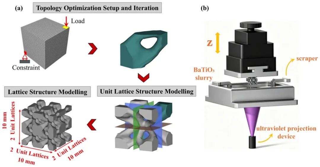
Density-based SIMP optimization maximizes stiffness within a 5 mm cubic cell. The source specifies a 500 MPa corner compression condition and a fixed opposite corner. Target solid fractions of 50%, 40% and 30% correspond to nominal porosities of 50%, 60% and 70%. Thresholding, surface smoothing and removal of isolated regions or excessively thin walls produce printable interconnected struts. A 2 × 2 × 2 array forms the 10 mm cubic design.
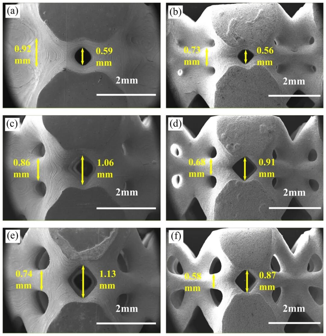
The slurry uses BaTiO₃ powder averaging 0.35 μm, ACMO monomer and 80% solids loading as stated in the source. Printed bodies undergo stepped nitrogen debinding, air treatment to remove residual carbon, then pressureless sintering at 1420 °C for two hours. Strut linear shrinkage stays near 21%, but pore shrinkage rises from 5.1% at 50% nominal porosity to 23.0% at 70%. Slender struts bend inward during sintering, so a single bulk shrinkage factor cannot reliably predict the final pore size.
3 · Phase and structural integrity
XRD identifies tetragonal perovskite P4mm in powder, green bodies and sintered specimens; the split (002)/(200) peaks near 2θ = 45° agree with PDF 75-1606, and the initial BaCO₃ impurity disappears after sintering. Raman bands near 254, 312, 517 and 725 cm⁻¹ support tetragonal ferroelectric order; a similar 312/517 intensity ratio across porosities suggests no measured porosity-induced lattice distortion.
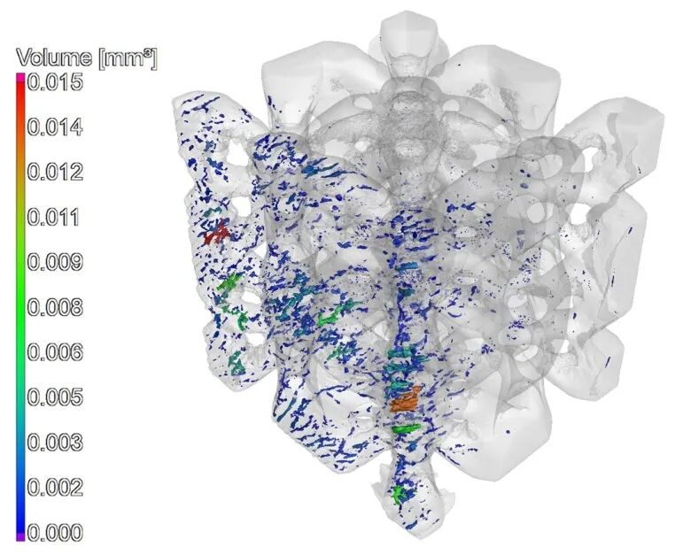
Equiaxed grains average 21.15 ± 5.81 μm. Mixed transgranular/intergranular fracture shows no obvious retained layer interfaces. Micro-CT of the 60% lattice finds 0.460 mm³ defects, 0.299% of structural volume, largely micropores below 150 μm equivalent diameter near the platform face. Removal stresses followed by thermal shrinkage are proposed causes; no through-cracks or extensive delamination are reported in the main skeleton. Companion solid specimens give 94.9% relative density and relative permittivity 1384.3.
4 · Strength falls as porosity rises
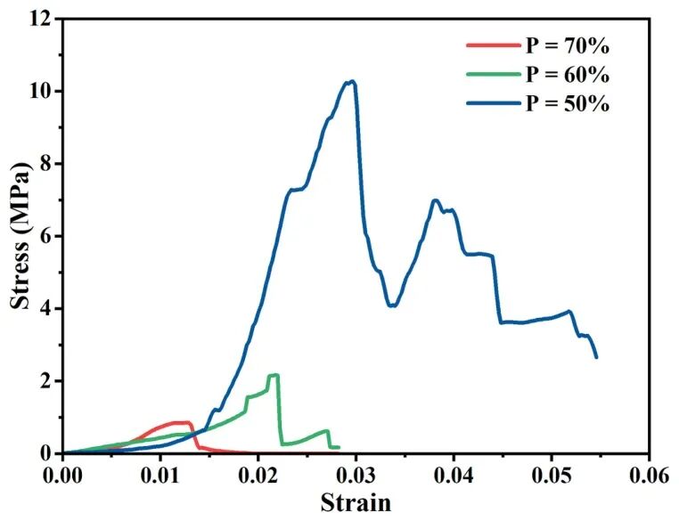
For 50%, 60% and 70% nominal porosity, respectively, elastic moduli are 613.30, 346.33 and 109.48 MPa, and ultimate compressive strengths are 9.81, 2.28 and 0.80 MPa. Thick, short struts at lower porosity are mainly crushed axially. Higher porosity produces slender members under combined compression and bending; the tensile side reaches fracture first, leading to a much steeper strength penalty.
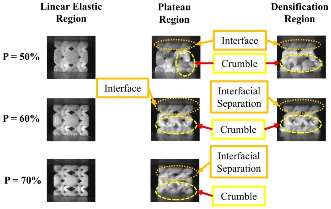
In-situ compression shows progressive layer collapse at 50% porosity, with an initial stress drop, a second peak and a longer plateau as neighboring intact regions take load. At 60% the plateau shortens and the second peak disappears. At 70%, the first local fracture triggers rapid global collapse. Thus, the highest voltage is not the mechanically most robust choice for repeated loading.
5 · Impact voltage and pulse width
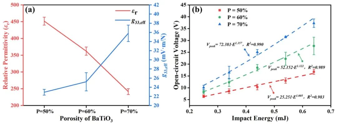
Apparent d₃₃ decreases only from 91.7 to 80.9 to 76.5 pC/N across the three porosities, a 16.6% overall reduction. Effective relative permittivity falls from 451.73 to 241.30; calculated g₃₃,eff rises through 22.9, 25.2 and 35.8 mV·m/N. Higher g₃₃ and increased local axial stress in the thinner struts jointly raise voltage; output is not determined by d₃₃ alone.
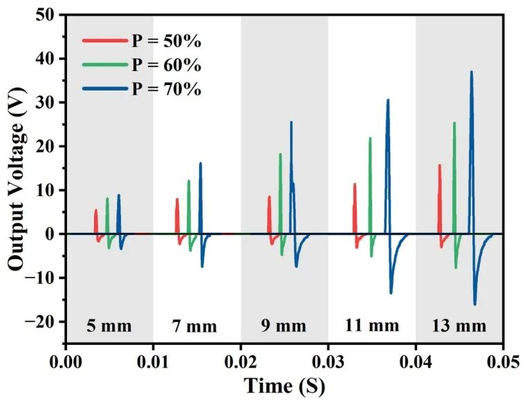
A 5 g steel ball dropped from 5–13 mm supplies 0.25–0.64 mJ. Voltage ranges are 6.43–16.76 V at 50% porosity, 8.20–27.68 V at 60% and 10.12–37.28 V at 70%. At 0.64 mJ, the 70% lattice gives 122% more peak voltage than the 50% one; fitted power laws have R² above 0.98. Unpolarized controls stay below a 5 mV noise threshold. The study reports stable waveforms over 50 consecutive impacts at the tested heights—not unlimited fatigue life.
The 70% lattice is also 82.2% less stiff than the 50% one. Longer mechanical contact broadens the voltage pulse, potentially easing acquisition bandwidth requirements but slowing transient response. High peak open-circuit voltage is neither delivered power nor a complete sensor specification; impedance, electronics, calibration and mechanical survival matter as well.
6 · Designing a continuous coupling path
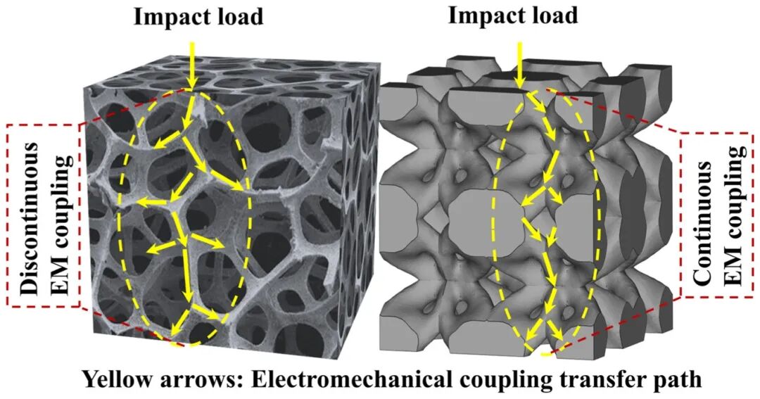
Random porous structures dissipate impact through local collapse and interrupted load paths. The optimized interconnected skeleton carries excitation through the piezoelectric phase. The source compares earlier printed BaTiO₃ devices below 0.3 V at much higher impact energy, but differing geometries and electrical setups prevent treating that comparison as a universal product ranking. The central result is that topology can tune voltage sensitivity and pulse shape without changing the material chemistry.
Evidence is limited to lead-free BaTiO₃, nominal 50–70% porosity and laboratory ball-drop loading. Long-duration cycling, humidity/temperature exposure, graded porosity, programmable anisotropy and sensor networks still need dedicated verification. Choose geometry jointly with the permissible load and electronics; the 37.28 V result is a conditional laboratory observation, not a guaranteed output of a DLP printer.
Sources
Original paper · DOI
Wang Y, Xu Y. Influence of porosities on compressive and impact piezoelectric properties of topology optimized BaTiO3 lattice structures fabricated via digital light processing. Ceramics International, 2026.